RCA DRC8320N User Guide - Page 8
Back of the DVD/VCR
 |
UPC - 034909520161
View all RCA DRC8320N manuals
Add to My Manuals
Save this manual to your list of manuals |
Page 8 highlights
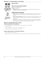
Chapter 1: Connections and Setup VIDEO AUDIO IN OUT S RF INPUT VIDEO AUDIO S OUTPUT Back of the DVD/VCR The back of your recorder might look a little overwhelming at first. This section explains what goes where and why. There are two sets of jacks on the back of your DVD recorder-INPUT jacks and OUTPUT jacks. Each jack is explained individually below, but the basic idea is about sending and receiving information to be played on or through your DVD recorder and displaying that information on your TV screen. INPUT The cables connected to the INPUT jacks bring pictures and sound INTO the DVD recorder, such as the cable signal (programming) from the cable company or satellite programming from a satellite receiver. OUTPUT The cables connected to the OUTPUT jacks are sending pictures and sound from the DVD recorder OUT TO your TV so you can see it on the screen. The correct cables must be connected to the DVD recorder's Output jacks and the corresponding Input Jacks on the TV so you can see the program on the TV. You must also tune the TV to the correct channel, called a Video Input Channel (for details, go to page 22). Explanation of Jacks (from left to right) RF IN: Connect an RF coaxial cable from an off-air antenna, cable box, or cable outlet to this jack. The cable is sending the programming from the source to the DVD/VCR. RF OUT: Connect an RF coaxial cable (provided) to this jack and to the Cable/Antenna Input jack on your TV. It is important to connect this cable so that your TV receives programming even when the DVD/VCR is turned off. INPUT: These jacks receive audio and video from a compatible component, such as a satellite receiver. Another set of Input Jacks (INPUT 2) are on the front of the DVD/VCR for temporarily connecting components such as a camcorder or a video game unit. VIDEO: Color coded yellow, the video cable you use with this jack provides better quality than an RF coaxial cable but isn't as good as S-Video. Connect corresponding video cable to the output jack of a compatible component, such as a satellite receiver or cable box. AUDIO L (left): Color coded white, connect corresponding audio cable to the output jack of a compatible component, such as a satellite receiver or cable box. AUDIO R (right): Color coded red, connect corresponding audio cable to the output jack of a compatible component, such as a satellite receiver or cable box. S-VIDEO IN: If your satellite receiver or cable box has an S-VIDEO output jack, connect the S-Video cable to this jack because it provides better picture quality than standard video (the yellow jack). OUT: If your TV has an S-Video jack, connect an S-Video cable to the TV's S-VIDEO jack and to this S-VIDEO OUT jack on the DVD/VCR to achieve better picture quality than standard video (the yellow jack). continues on next page... 6 Graphics contained within this publication are for representation only.
-
 1
1 -
2
-
 3
3 -
 4
4 -
 5
5 -
 6
6 -
 7
7 -
 8
8 -
 9
9 -
 10
10 -
 11
11 -
 12
12 -
 13
13 -
14
-
15
-
16
-
17
-
18
-
19
-
20
-
21
-
22
-
23
-
24
-
25
-
26
-
27
-
28
-
29
-
30
-
31
-
32
-
33
-
34
-
35
-
36
-
37
-
38
-
39
-
40
-
41
-
42
-
43
-
44
-
45
-
46
-
47
-
48
-
49
-
50
-
51
-
52
 |
 |
