RCA MAF15BKR Owner/User Manual - Page 2
Mounting the wall plate
 |
View all RCA MAF15BKR manuals
Add to My Manuals
Save this manual to your list of manuals |
Page 2 highlights
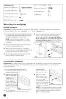
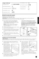
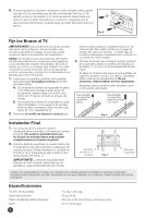
Hardware Kit (A) M8 x 63 Lag Bolt (x3) (B) Lag Bolt Washer (x3) (C) Concrete Anchor (x3) (D) M4 x 12 Screw (x4) (E) M4 x 20 Screw (x4) (F) M6 x 12 Screw (x4) (G) M6 x 20 Screw (x4) (H) M6 Washer (x4) (I) Spacer (x4) Mounting the wall plate Drywall Installation Important! For safety reasons, this mount must be secured to a wood stud capable of supporting the combined weight of the mount and display. Do not mount to drywall alone. 1. Use a high quality stud finder to locate a stud where you wish to install your mount. Mark both edges of the stud to help identify the exact center. NOTE: You must use the center of the stud to avoid cracking or splitting the wood during installation. 2. Place the wall plate against the wall and level it using the integrated bubble level. 3. While another person holds the wall plate in position, mark two locations (top and bottom) for securing the mount to the wall. (see Fig.1). 4. Set the wall plate aside and drill a 6 mm (1/4") pilot hole at each marked location. 5. Place the wall plate back against the wall and attach it using the lag bolts (A) and lag bolt washers (B) (see Fig. 2). Do not over-tighten these bolts and do not release the wall plate until all bolts are in place. Ensure that the wall plate remains level after all bolts are secured. Fig.1 Fig.2 Concrete/Brick Installation IMPORTANT! For safety reasons, the concrete wall must be capable of supporting the combined weight of the mount and the display. The manufacturer takes no responsibility for failure caused by walls of insufficient strength. 1. Place the wall plate against the wall in the desired location and level it using the integrated bubble level. 2. While another person holds the wall plate in place, mark three locations on the wall for securing the mount. Mark two locations at the top of the wall plate and one location at the bottom of the wall plate (see Fig. 3). Fig.3 3. Set the wall plate aside and drill a 10 mm (3/8") hole at each marked location. Remove any excess dust from the holes. 4. Insert a Concrete Anchor (C) into each hole so that it is flush with the concrete surface (see Fig. 4). A hammer can be used to lightly tap the anchors into place if necessary. Fig.4 NOTE: If the concrete wall is covered by a layer of plaster or drywall, the concrete anchor must pass completely through the layer to rest flush with the concrete surface. 2
-
 1
1 -
 2
2 -
 3
3 -
 4
4 -
 5
5 -
 6
6 -
 7
7 -
 8
8 -
9
-
10
-
11
-
12
 |
 |
