RCA MAF15BKR Owner/User Manual - Page 3
Attaching the Arms to the TV, Specifications, Final Installation
 |
View all RCA MAF15BKR manuals
Add to My Manuals
Save this manual to your list of manuals |
Page 3 highlights
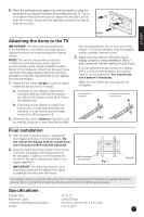
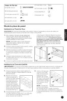
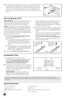
5. Place the wall plate back against the wall and attach it using the lag bolts (A) and lag bolt washers (B) provided (see Fig. 5). Do not over-tighten these bolts and do not release the wall plate until all bolts are in place. Ensure that the wall plate remains level after all bolts are secured. English Fig.5 Attaching the Arms to the TV IMPORTANT! Use extra care during this part of the installation. If possible, avoid placing your display facedown as it may damage the viewing surface. NOTE: This mount comes with a selection of different screw diameters and lengths to accommodate a wide variety of display models. Not all of the hardware in the kit will be used. If you cannot find the appropriate screw size in the kit provided, consult the manufacturer of your display for more information. 1. Determine the correct length of screw to use by examining the back of your display: A. If the back of your display is flat and the mounting holes are flush with the surface, you will use the shorter screws (D or F) from the hardware kit. B. If the back of your display is curved, has a protrusion, or if the mounting holes are recessed, you will need to use the longer screws (E or G) and spacers (I). 2. Determine the correct diameter of screw to use by carefully trying one of each size (M4 and M6) from the hardware kit. Do not force any of the screws - if you feel resistance stop immediately and try a smaller diameter screw. 3. Attach the mount arms to the back of your display using the screws identified in Steps 1 and 2 along with the M6 washers (H) (see Fig.6). If you are using the longer screws on a display with a curved or recessed back, you will also need to use the spacers (I). You should only use a spacer if necessary. Make sure the screws are snug, but do not overtighten. For displays with For displays with curved or recessed backs. Fig.6 Final Installation 1. With the help of another person, carefully lift your display and place it on the wall plate. Do not release the display until the mount arms have securely hooked onto the wall plate. 2. Insert the safety bar at the bottom of the mount to prevent the display from being lifted from the wall plate. A padlock can be inserted into the end of the bar to help prevent theft of your display (see Fig.7). IMPORTANT! The safety bar must be used at all times to prevent the display from being accidentally knocked from the mount. Padlock (optional, not included) Fig. 7 Safety Bar Periodically clean your mount with a dry cloth. Inspect all screws and hardware at regular intervals to ensure that no connections have become loose over time. Re-tighten as necessary. Specifications Display Size: 15" to 32" Maximum Load: 25 kg (55 lbs) Universal VESA Mounting Pattern: 230 mm x 250 mm (9" x 9.8") max Profile: 2.2 cm (0.9") 3
-
 1
1 -
 2
2 -
 3
3 -
 4
4 -
 5
5 -
 6
6 -
 7
7 -
 8
8 -
 9
9 -
10
-
11
-
12
 |
 |
