RCA WSP155 Owner/User Manual: WSP155 - Page 3
Transmitter, Speaker, Supplied Accessories, Installation - receiver
 |
UPC - 079000332367
View all RCA WSP155 manuals
Add to My Manuals
Save this manual to your list of manuals |
Page 3 highlights
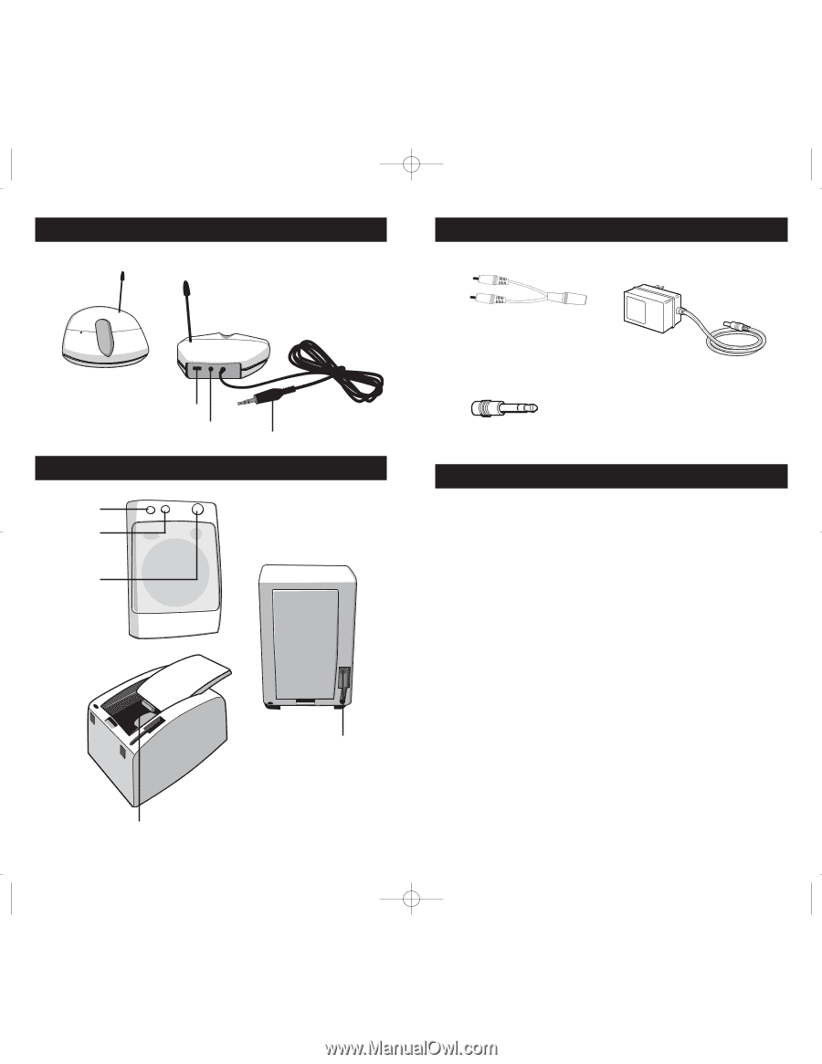
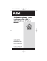
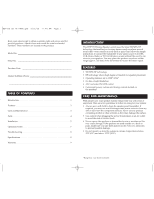
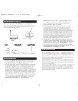
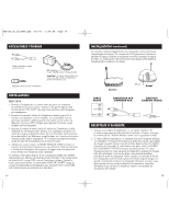
WSP155_US_IB_REVB.qxd 5/1/07 11:48 AM Page 4 TRANSMITTER Transmitter Front Transmitter Back Channel selection control 1, 2, 3 DC power supply socket Audio input plug SPEAKER Bass boost button Auto scan button Power on/off and volume knob Speaker Front Speaker Back DC IN power supply socket Battery compartment 4 SUPPLIED ACCESSORIES Stereo Y adapter cable (RCA/3.5 mm jack) 3.5 mm/6.35 mm jack adapter (3) AC power adapters (1 for transmitter, and 1 each for the speakers) Important: These power units are intended to be correctly oriented in a vertical or floor mount position. INSTALLATION TRANSMITTER 1. Plug the supplied AC power adapter into an electrical outlet near your audio source. Make sure it is the one for the transmitter ("DC 12.5V")-the two for the speakers are marked accordingly. 2. Connect the plug end of the power adapter to the DC jack located on the back of the transmitter (see diagram). The green LED indicator light on the top panel will glow when an active audio source is detected. The LED indicates the unit is transmitting which indicates the unit is receiving power. 3. Locate the audio input cord on the back of the transmitter. The 3.5 mm standard plug can be used to fit most headphone output jacks in audio equipment. If you are connecting to the audio output jacks from a TV, amplifier, etc. then plug the audio input cord into the "Y" adapter that is provided to adapt standard RCA type audio plugs for the audio source. 4. Turn on the audio source. The CHANNEL SELECTION CONTROL is located on the back of the transmitter. Select the desired channel by using the switch on the back of the transmitter. This channel can later be switched to achieve optimal audio reception. This speaker system has automatic ON/OFF control that automatically turns the transmitter on if there is an audio signal detected and the green LED light on the top of the transmitter will glow. Once the audio source is switched off, the ON/OFF control will turn off power and stop transmitting to the speakers and the green LED will be off (after a 4 minutes timeout period). 5
-
 1
1 -
 2
2 -
 3
3 -
 4
4 -
 5
5 -
 6
6 -
 7
7 -
 8
8 -
 9
9 -
10
-
11
-
12
-
13
-
14
-
15
 |
 |