Reebok Cyc31 Uk Manual - Page 7
Handlebar Post 6 so that the Handlebar Post
 |
View all Reebok Cyc31 manuals
Add to My Manuals
Save this manual to your list of manuals |
Page 7 highlights
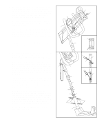
5. The Console (9) requires two "AA" batteries (not included); alkaline batteries are recommended. Press two batteries into the battery clip on the back of the Console (see the inset drawing). Make sure that the negative (-) ends of the batteries are touching the springs in the battery clip. While another person holds the Console (9) near the Console Plate (8), connect the Extension Wire (22) to the console wire. Insert all excess wiring down into the Handlebar Post (6); make sure that the Resistance Cable (16) is positioned as shown. Attach the Console (9) to the Console Plate (8) with six Console Screws (20). Firmly press the Resistance Knob (51) onto the Resistance Control (16). 5 16 7 20 9 51 Console Wire 22 16 8 Battery Clip 6 6. While another person holds the Handlebar Post (6) near the Frame (1) as shown, connect the 6 Extension Wire (22) to the Reed Switch Wire (44). Batteries A 9 17 Next, connect the Resistance Cable (16) to the Extension Cable (17) as shown in drawings A and B. First, insert the tip of the Resistance Cable (16) into the wire clip on the Extension Cable (17) as 52 shown in drawing A. Next, firmly pull the Resistance Cable and slide it into the metal bracket as shown in drawing B. Jack 16 B 17 Insert the Handlebar post (6) into the Frame (1). Be careful not to pinch the wires and cables. Slide the Round Collar (13) down the Handlebar Post and press it into the Frame. Secure the Round Collar with an M6 x 10mm Screw (26). 13 16 6 Note: There are two sets of holes in the Handlebar Post (6) so that the Handlebar Post can be attached at either of two height settings. Choose the setting that you think will be the most comfortable. Secure the Handlebar Post (6) to the Frame (1) with four M8 x 25mm Button Screws (27) and four M8 Curved Washers (28). 16 17 26 27 28 22 44 28 27 Plug the Pulse Monitor (52) into the jack on the left side of the Console (9). 1 7
-
 1
1 -
 2
2 -
 3
3 -
 4
4 -
 5
5 -
 6
6 -
 7
7 -
 8
8 -
 9
9 -
 10
10 -
 11
11 -
 12
12 -
13
-
14
-
15
-
16
 |
 |
