Reebok S 9.80 Treadmill English Manual - Page 9
Aged When The Power Is Turned On.
 |
View all Reebok S 9.80 Treadmill manuals
Add to My Manuals
Save this manual to your list of manuals |
Page 9 highlights
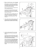
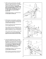
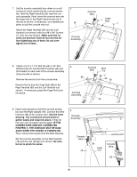
7. Set the console assembly face down on a soft surface to avoid scratching the console assembly. Hold the Right Handrail (95) near the console assembly. Next, insert the console wire into the large hole in the Right Handrail and out of the top as shown. If necessary, use needlenose pliers to pull the console wire out. Attach the Right Handrail (95) and the Left Handrail (not shown) with four #8 x 3/4" Screws (1) (only two are shown). Make sure that no wires are pinched. Start all four Screws before tightening any of them; do not overtighten the Screws. 7 95 Console Assembly Console Wire Large 1 Hole 1 8. Tighten a 1/4" x 1 1/4" Bolt (5) with a 1/4" Star Washer (33) into the Handrail Crossbar (94) and the bracket on each side of the console assembly (only one side is shown). Remove the wire tie from the console wire. Remove the tie from the Cage Nuts (88) in the Right Handrail (95) and the Left Handrail (not shown). If necessary, press the Cage Nuts back into place. 8 Console Wire Wire Tie 5 88 33 95 Console Assembly 94 9. Have a second person hold the console assembly near the Right Upright (78). Connect the Wire Harness (38) to the console wire. See the inset drawing. The connectors should slide together easily and snap into place. If they do not, turn one connector and try again. IF THE CONNECTORS ARE NOT CONNECTED PROPERLY, THE CONSOLE MAY BE DAMAGED WHEN THE POWER IS TURNED ON. Then, remove the long tie from the Wire Harness. Set the console assembly on the Right Upright (78) and the Left Upright (not shown). Be careful not to pinch the wires. 9 Console Assembly Console Wire 78 38 Long Tie Console Wire 38 9
-
 1
1 -
2
-
3
-
 4
4 -
 5
5 -
 6
6 -
 7
7 -
 8
8 -
 9
9 -
 10
10 -
 11
11 -
 12
12 -
 13
13 -
 14
14 -
15
-
16
-
17
-
18
-
19
-
20
-
21
-
22
-
23
-
24
-
25
-
26
-
27
-
28
-
29
-
30
-
31
-
32
 |
 |
