Reebok V 6.80 Treadmill English Manual - Page 10
Lower the Frame 52 see HOW TO LOWER - v 6 8 treadmill
 |
View all Reebok V 6.80 Treadmill manuals
Add to My Manuals
Save this manual to your list of manuals |
Page 10 highlights
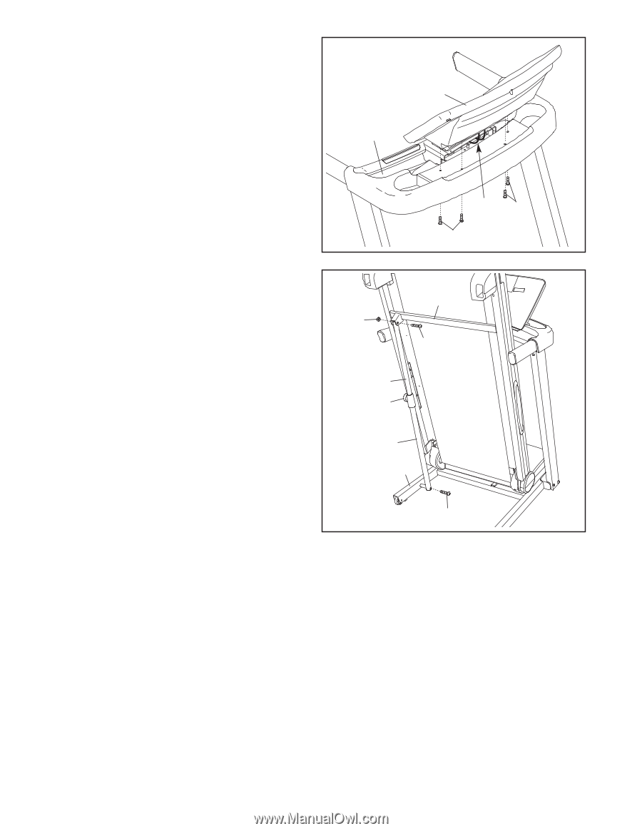
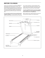
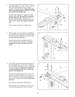
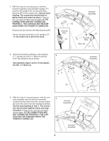
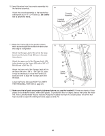
10. Insert the wires from the console assembly into the handrail assembly. Attach the console assembly to the handrail assembly with four 1/4" x 3/4" Bolts (5). Be careful not to pinch the wires. 10 Console Assembly Handrail Assembly Wires 5 5 11. Raise the Frame (52) to the position shown. Have a second person hold the Frame until this step is completed. Orient the Storage Latch (49) so that the large barrel and the Latch Knob (50) are in the positions shown. Attach the upper end of the Storage Latch (49) to the bracket on the Frame (52) with a 3/8" x 2" Bolt (6) and a 3/8" Nut (7). Attach the lower end of the Storage Latch (49) to the Base (84) with a 3/8" x 1 3/4" Bolt (2). Note: It may be necessary to move the Frame (52) back and forth to align the Storage Latch with the Base. Lower the Frame (52) (see HOW TO LOWER THE TREADMILL FOR USE on page 21). 11 7 52 6 49 50 Large Barrel 84 2 12. Make sure that all parts are properly tightened before you use the treadmill. If there are sheets of clear plastic on the treadmill decals, remove the plastic. To protect the floor or carpet, place a mat under the treadmill. Note: Extra hardware may be included. Keep the included hex keys in a secure place; one of the hex keys is used to adjust the walking belt (see pages 23 and 24). 10
-
 1
1 -
2
-
3
-
4
-
 5
5 -
 6
6 -
 7
7 -
 8
8 -
 9
9 -
 10
10 -
 11
11 -
 12
12 -
 13
13 -
 14
14 -
 15
15 -
16
-
17
-
18
-
19
-
20
-
21
-
22
-
23
-
24
-
25
-
26
-
27
-
28
-
29
-
30
-
31
-
32
 |
 |