Rheem Versa Heaters Operating Instructions - Page 24
Gas Valve Removal, Main Burner & Orifice Removal, Igniter Removal & Cleaning, Electronic,
 |
View all Rheem Versa Heaters manuals
Add to My Manuals
Save this manual to your list of manuals |
Page 24 highlights
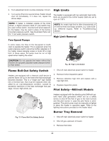
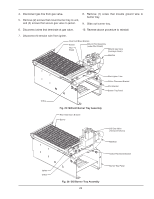
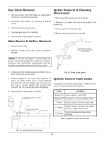
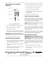
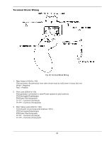
Gas Valve Removal 1. Remove burner tray from heater as described in the Burner Tray Removal section. 2. Disconnect pilot tubing (if removing a Millivolt valve). 3. Disconnect wires to gas valve. 4. Unscrew gas valve from manifold. 5. Reverse above procedure to reinstall. Igniter Removal & Cleaning (Electronic) 1. Disconnect high tension wire from igniter. 2. Remove (2) screws that mount the igniter to the burner tray. 3. Remove igniter from burner tray. 4. Reverse above procedure to reinstall. Main Burner & Orifice Removal 1. Remove burner tray. 2. Remove screws from rear burner hold-down bracket. NOTE: If the heat exchanger is sooted badly, the burner hold-down bracket and spacer can become distorted from direct-flame impingement and this usually necessitates replacement of these parts. 3. Lift burners from slotted spacers and slide from orifices. Clean with a wire brush. Fig. 32: Direct Spark Igniter 4. Orifices usually do not need to be replaced. To clean, run either copper wire or wood toothpick through orifice. Do not enlarge hole. To remove orifice, use a socket wrench and remove from manifold. Do not over-tighten when reinstalling. Ignition Control Fault Codes The ignition control fault codes listed in Table H can be used to troubleshoot ignition problems. 5. Reverse above procedure to reinstall. ORIFICES MUST BE PARALLEL WITH BASE TOLERANCE OF +2° -0° IGNITER BETWEEN IGNTER & BURNER PORTS 0.375" ± 0.125" BURNER PORTS Code Condition Steady On Power applied, control OK Steady Off No power or control hardware fault 1 Flash Ignition lockout from too many trials 2 Flashes Ignition lockout from too many flame losses in single call for heat 3 Flashes Control hardware/software fault detected Table H: Ignition Control Fault Codes Fig. 31: Igniter Position to Burners 24
-
 1
1 -
2
-
3
-
4
-
5
-
6
-
7
-
8
-
9
-
10
-
11
-
12
-
13
-
14
-
15
-
16
-
17
-
18
-
 19
19 -
 20
20 -
 21
21 -
 22
22 -
 23
23 -
 24
24 -
 25
25 -
 26
26 -
 27
27 -
 28
28 -
 29
29 -
30
-
31
-
32
-
33
-
34
-
35
-
36
 |
 |
