Rheem Versa Heaters Operating Instructions - Page 25
Pilot Removal & Cleaning, Millivolt, Heat Exchanger Removal, Tube Cleaning Procedure, De-sooting
 |
View all Rheem Versa Heaters manuals
Add to My Manuals
Save this manual to your list of manuals |
Page 25 highlights
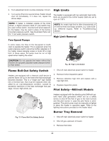
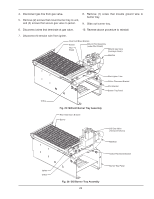
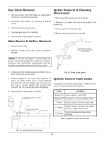
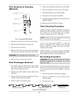
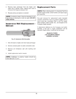
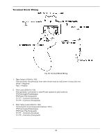
Pilot Removal & Cleaning (Millivolt) Thermopile Pilot Air Opening Orifice 5. Disconnect all electrical wiring from in/out header. 6. Remove temperature sensor from in/out header. 7. Disconnect flange nuts on In/Out header. 8. Set aside heat exchanger side baffles. 9. Lift heat exchanger straight up using caution not to damage refractory. 10. Reverse above procedure to reinstall. Tube Cleaning Procedure Establish a regular inspection schedule, the frequency depending on the local water conditions and the severity of service. Do not let the tubes clog up solidly. Clean out deposits over 1/16" in thickness. Fig. 33: Honeywell Millivolt Pilot 1. Disconnect pilot tubing and wires from gas valve. 2. Remove pilot assembly from burner tray. 3. Remove pilot from bracket. NOTE: Please remove heat exchanger from heater prior to reaming or removing debris. Use the Tube Cleaning Kit #052871F to ream the tubes as necessary. After reaming, mount the wire brush in place of the auger and clean out debris remaining in the tubes. 4. Remove pilot orifice and air opening (Honeywell MV unit only), and clean with wire or small brush. CAUTION: Do not enlarge hole in pilot orifice. 5. Reverse above procedure to reinstall. Heat Exchanger Removal Another method is to remove the heat exchanger, ream tubes and immerse heat exchanger in non-inhibited de-scale solvent for severe scale build-up. De-sooting Procedure CAUTION: Soot may be combustible. Wet sooted surfaces completely prior to cleaning. Do not use steel wire brush. 1. Shut water, gas and electricity off, close valves and relieve pressure, then remove relief valve. Remove side inspection panels. 2. Remove top jacket holding screws. Remove the jacket top. Soot will clog areas between fins and cause eventual tube failure. Any sign of soot at the base of the burners or around the outer jacket indicates a need for cleaning. 1. Remove top and flue collector from cabinet. 3. Remove the four (4) screws holding down the flue 2. Remove "V" baffles from heat exchanger, includ- collector. Remove the flue collector. ing side baffles. 4. Remove upper in/out access panel. 3. Remove burner tray. Extension Pieces (2) Auger with Carbide Tip Fig. 34: Tube Cleaning Kit 25 Wire Brush
-
 1
1 -
2
-
3
-
4
-
5
-
6
-
7
-
8
-
9
-
10
-
11
-
12
-
13
-
14
-
15
-
16
-
17
-
18
-
19
-
 20
20 -
 21
21 -
 22
22 -
 23
23 -
 24
24 -
 25
25 -
 26
26 -
 27
27 -
 28
28 -
 29
29 -
 30
30 -
31
-
32
-
33
-
34
-
35
-
36
 |
 |
