Ridgid K-75 Owners Manual - Page 16
K-1500SP Wiring Diagram
 |
View all Ridgid K-75 manuals
Add to My Manuals
Save this manual to your list of manuals |
Page 16 highlights
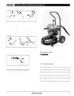
K-75A/B, K-1500A/B, & K-1500SP Drain Cleaning Machines K-1500SP Wiring Diagram 120V/60 Hz Ground Screw in Switchbox R Bk Y WO Switch For Rev Rev For W L2 L1 Bk W U1 Y U2 Bk Z1 1 R Bl Bl Service Cord Green L2 White L1 Black Line cord Modification: Cut off existing terminals Strip Wire Ends .25 in. Green White Black K-1500SP Wiring Diagram 220-240V/50 Hz Ground Screw in Switchbox Rev Y Bk Switch For For Rev Bl Br L2 L1 Bl R OW Bk Y Bl Green-Yellow L2 Brown L1 Blue 14 Line cord Modification: Strip Wire Ends .25 in. Ridge Tool Company NOTE: Switch modified using provided jumper terminals. Green-Yellow Brown Blue
-
 1
1 -
2
-
3
-
4
-
5
-
6
-
7
-
8
-
9
-
10
-
 11
11 -
 12
12 -
 13
13 -
 14
14 -
 15
15 -
 16
16 -
 17
17 -
 18
18 -
 19
19 -
 20
20 -
 21
21 -
22
-
23
-
24
-
25
-
26
-
27
-
28
-
29
-
30
-
31
-
32
-
33
-
34
-
35
-
36
-
37
-
38
-
39
-
40
-
41
-
42
-
43
-
44
-
45
-
46
-
47
-
48
-
49
 |
 |

K-75A/B, K-1500A/B, & K-1500SP Drain Cleaning Machines
Ridge Tool Company
14
K-1500SP Wiring Diagram
120V/60 Hz
K-1500SP Wiring Diagram
220-240V/50 Hz
Switch
Bk
Switch
Service Cord
W
O
Y
R
Y
W
W
Bl
Ground
Screw in
Switchbox
For
Rev
L2
L1
Bk
U1
U2
Bl
Green
L2 White
L1 Black
Rev
Bk
For
Z1
1
R
Green
Black
White
Line cord Modification:
Cut off existing terminals
Strip Wire Ends .25 in.
Y
L2
L1
Bl
Green-Yellow
L2 Brown
L1 Blue
Rev
Bk
For
Green-Yellow
Brown
Line cord Modification:
Strip Wire Ends .25 in.
Blue
For
Rev
Bl
Br
Ground
Screw in
Switchbox
Bk
W
O
Y
R
Bl
NOTE: Switch modified using
provided jumper terminals.