Ridgid RD8000 Owners Manual - Page 12
Connecting Battery, Warning, Removable Control Panel, Installing A Wall Mount For - cable locator
 |
View all Ridgid RD8000 manuals
Add to My Manuals
Save this manual to your list of manuals |
Page 12 highlights
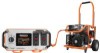
assembly Raise the handle end of the generator high enough to gain access to the frame bottom; securely position props underneath to support. Insert an axle through the center of the wheel. Place a washer on the axle, then slide the axle through the bracket on the frame. Slide the hitch pin through the hole in the axle and make sure it is secure. Repeat the process on the other side to install second wheel. connecting battery See Figure 7. The battery cables must be connected before the electric start feature of the generator can be operated. Connect the red wire to the positive (+) terminal first, then connect the black wire to the negative (−) terminal using the bolts, nuts, and washers provided. Make sure all connections are tight. NOTE: Be careful not to short across the terminals when installing. Shorting the terminals together can cause sparks, damage to the battery or generator, or even burns or explosions. Cover the terminals with the rubber covers. When removing the battery for replacement: remove the nut and bolt first from the negative (black) post, then from the positive (red) post, being careful not to short across the terminals. Always abide by the safety warnings provided with the battery. Remove the battery and dispose of according to local and state regulations. WARNING: To reduce the risk of electrocution or explosion, do not short circuit the battery terminals or charge in a sealed container. Keep sparks and flame away. WARNING: Keep metal objects away from the battery terminals. Metal objects can make a connection from one terminal to another. Shorting the battery terminals together may cause sparks, burns, or a fire. REMOVABLE CONTROL PANEL See Figure 8. To detach the removable control panel from the generator: Turn off the generator. Loosen the latch on the removable control panel and pull the control panel forward. Disconnect the twist-lock plug and the 12V engine control connector on the back of the control panel. installing A WALL MOUNT FOR THE removable control panel See Figure 9 - 10 The removable control panel can be removed from the generator and wall-mounted in another location before reconnecting it to the generator. To wall-mount the removable control box: Screws or nails for hanging the box should be spaced 4-1/4 in. from center to center. Mark the 4-1/4 in. measurement on a wall stud or other sturdy wood surface. Drill holes and insert the screws; tighten the screws securely into the wood. If using nails, the nail head should be large enough to hold the control panel securely. NOTE: There should be at least 5/8 in. of the screw or nails protruding from the wood piece for hanging the box. Hang the box on the screws or nails, making certain it is secure. 12 - English
-
 1
1 -
2
-
3
-
4
-
5
-
6
-
 7
7 -
 8
8 -
 9
9 -
 10
10 -
 11
11 -
 12
12 -
 13
13 -
 14
14 -
 15
15 -
 16
16 -
 17
17 -
18
-
19
-
20
-
21
-
22
-
23
-
24
-
25
-
26
-
27
-
28
-
29
-
30
-
31
-
32
-
33
-
34
-
35
-
36
-
37
-
38
-
39
-
40
-
41
-
42
-
43
-
44
-
45
-
46
-
47
-
48
-
49
-
50
-
51
-
52
-
53
-
54
-
55
-
56
-
57
-
58
-
59
-
60
-
61
-
62
-
63
-
64
-
65
-
66
-
67
-
68
-
69
-
70
-
71
-
72
-
73
-
74
 |
 |
