Rocketfish RF-RBWS02 User Manual (English) - Page 9
Sender/receiver (front panel), HUB STATUS, SOURCE - ac power adapter
 |
View all Rocketfish RF-RBWS02 manuals
Add to My Manuals
Save this manual to your list of manuals |
Page 9 highlights
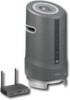
Sender/receiver (front panel) TM 1 23 4 567 # Feature 1 Power/Join button Description Press to turn the sender/receiver on. Press and hold to initiate joining. Press again to go to standby mode. When you connect the AC power adapter, the device turns on automatically. Power/Join indicator Lights blue when the HUB STATUS switch is set to DISABLE. Lights green when the HUB STATUS switch is set to ENABLE. 2 The indicator will turn solid when it is joined in a network, if the device is not in a network, the indicator blinks slowly. When the device is put in joining mode, the indicator blinks rapidly. 3 Standby indicator Turns red when the sender/receiver is in standby mode. 4 Remote control sensor Receives the signal from the remote control. window 5 Source Press to select different audio streams on your Rocketboost network. Each press moves to the next source. Receiver mode indicator Turns blue when receiving audio from a Rocketboost sender. Blinks slowly if the current 6 source listened to is muted. Note: This indicator will not be lit if the Rocketboost sender is turned off. Press the SOURCE button to find the next available source. Sender mode indicator Turns blue when sending audio. 7 Note: This indicator will light automatically when a 3.5 mm connector is attached to the device (the device senses the cable connection). RF-RBWS02 9
-
 1
1 -
2
-
3
-
 4
4 -
 5
5 -
 6
6 -
 7
7 -
 8
8 -
 9
9 -
 10
10 -
 11
11 -
 12
12 -
 13
13 -
 14
14 -
15
-
16
-
17
-
18
-
19
-
20
-
21
-
22
-
23
-
24
-
25
-
26
-
27
-
28
-
29
-
30
-
31
-
32
-
33
-
34
-
35
-
36
-
37
-
38
-
39
-
40
 |
 |
