Ryobi BD4600 English Manual - Page 12
Assembly - drive belt
 |
View all Ryobi BD4600 manuals
Add to My Manuals
Save this manual to your list of manuals |
Page 12 highlights
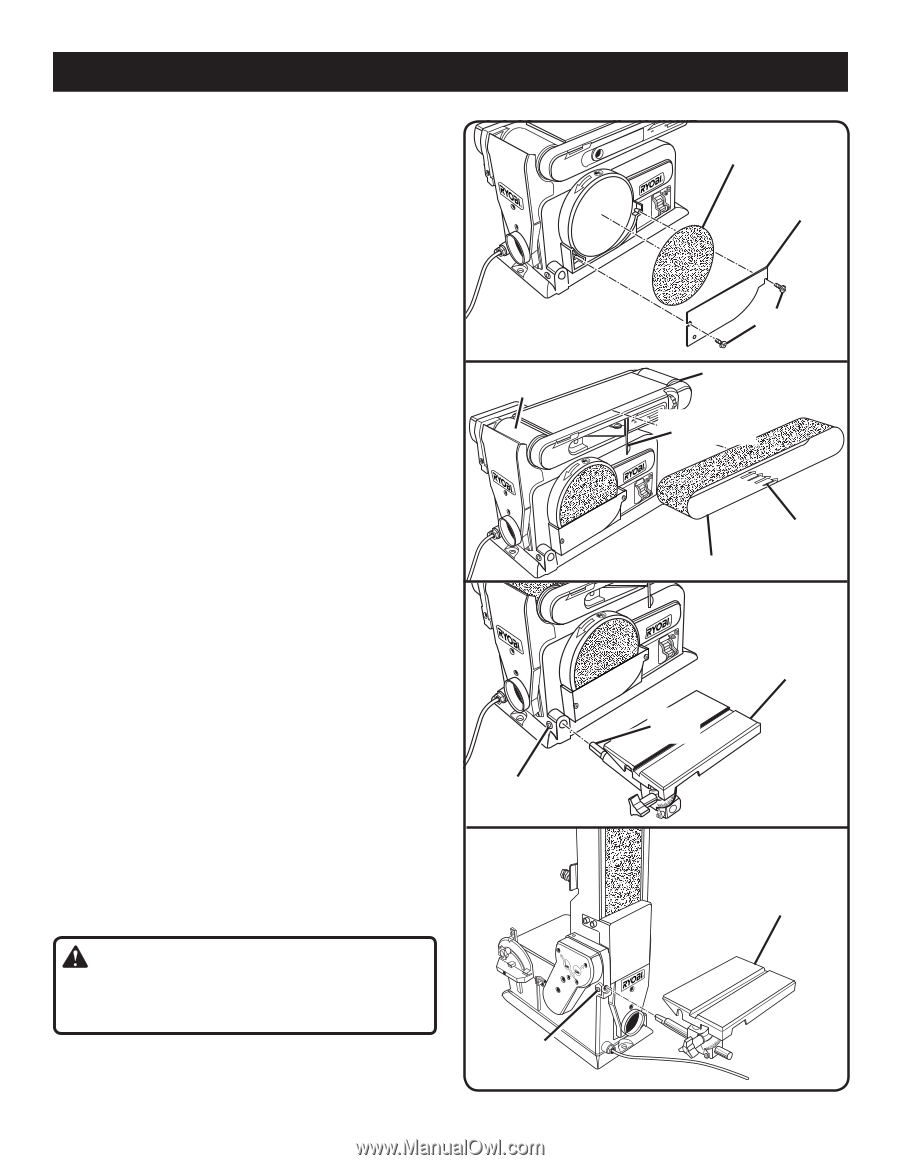
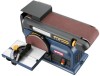
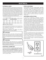
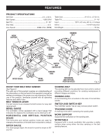
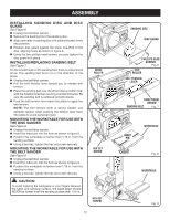
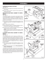
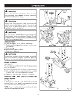
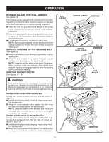
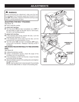
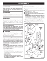
assembly INSTALLING SANDING DISC AND DISC GUARD See Figure 6. n Unplug the belt/disc sander. n Remove the backing from the sanding disc. n Align perimeter of sanding disc with plate and press firmly into position. n Position disc guard against the lower one-third of the disc, aligning holes as shown in figure 6. n Using the two phillips head screws, securely tighten the disc guard into place. installing/REPLACING sanding belt See Figure 7. On the smooth side of the sanding belt, there is a directional arrow. The sanding belt must run in the direction of the arrow. n Unplug the belt/disc sander. n Pull the belt tension lever toward you to release belt tension. n Place the sanding belt over the drive roller and idler roller with the directional arrows running counterclockwise. Be sure the sanding belt is centered on both drums. n Push the belt tension lever back into place to apply the belt tension. NOTE: The belt tension lever is spring loaded; use extreme caution when pushing the tension lever back into place to avoid personal injury. mounting the worktable for use with the disc sander See Figure 8. n Unplug the belt/disc sander. n Insert the index pin into the hole as shown in figure 8. n Position the worktable no farther than 1/16 in. from the sanding surface. n Using a hex key, tighten the hex set screw securely. mounting the worktable for use with the belt sander See Figure 9. n Unplug the belt/disc sander. n Insert the index pin into the hole as shown in figure 9. n Position the worktable no farther than 1/16 in. from the sanding surface. n Using a hex key, tighten the hex set screw securely. caution: To avoid trapping the workpiece or your fingers between the table and sanding surface, the table edge should NEVER be further from the sanding surface than 1/16 in. Drive roller HEX set screw HEX set screw 12 4 x36 sanding disc DISC GUARD PHILLIPS HEAD SCREWS Fig. 6 iDLe roller 4 x36 BeLT TENSION lever DIRECTIONAL ARROW 4 x36SANDING BELT Fig. 7 INDEX PIN WORKTABLE Fig. 8 WORKTABLE Fig. 9
-
 1
1 -
2
-
3
-
4
-
5
-
6
-
 7
7 -
 8
8 -
 9
9 -
 10
10 -
 11
11 -
 12
12 -
 13
13 -
 14
14 -
 15
15 -
 16
16 -
 17
17 -
18
 |
 |