Ryobi RY48130 Operation Manual - Page 23
Warning
 |
View all Ryobi RY48130 manuals
Add to My Manuals
Save this manual to your list of manuals |
Page 23 highlights
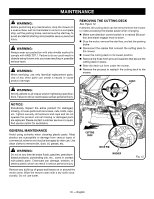
MAINTENANCE Stop the motor and remove the start key. Raise the mower seat. Disconnect the quick-connect plug. This plug connects the seat to the safety interlock system. Remove and set aside the hex head bolts and nuts that secure the seat. Press the tabs on the wiring cover. Lift the cover and set to one side to gain access to the compartment below. Disconnect the battery quick-connect plug. This plug connects the batteries to the mower. Remove the two Phillips screws that secure the the panel next to the control panel. Loosen, but do not remove, the four Phillips screws that secure the control panel. Remove the 10 Torx screws that secure the shroud of the mower in place. Remove the top shroud and panel from the mower. Remove and set aside the hex head bolt that secures the battery bracket in place. PANEL WARNING: Under extreme usage or temperature conditions, battery leakage may occur. If liquid comes in contact with your skin, wash immediately with soap and water. If liquid gets into your eyes, flush them with clean water for at least 10 minutes, then seek immediate medical attention. Following this rule will reduce the risk of serious personal injury. Lift the battery securing bracket off the batteries and set aside. Remove and set aside the battery covers for the battery or batteries being replaced. Disconnect the battery or batteries you wish to replace. Disconnect the negative (black) cable first, then the positive (red) cable, being careful not to short across the terminals. Replace battery or batteries as needed and reinstall cables. Connect the positive (red) cable first, then the negative (black) cable, being careful not to short across the terminals. Reinstall the battery covers and the battery securing bracket. Reinstall hex head bolt to secure battery tray in place. Tighten securely. Reinstall the shroud and panel and their screws in the reverse order of removal. Tighten securely. NOTE: Make sure the tabs on the panel and shroud are seated in the slots on the mower base and control panel before tightening screws. HEX HEAD BOLT RED ( + ) BLACK ( - ) 23 - English SHROUD SCREWS Fig. 20 BATTERY BRACKET BATTERY COMPARTMENT COVERS BOLT WASHER LOCK WASHER Fig. 21
-
 1
1 -
2
-
3
-
4
-
5
-
6
-
7
-
8
-
9
-
10
-
11
-
12
-
13
-
14
-
15
-
16
-
17
-
 18
18 -
 19
19 -
 20
20 -
 21
21 -
 22
22 -
 23
23 -
 24
24 -
 25
25 -
 26
26 -
 27
27 -
 28
28 -
29
-
30
-
31
-
32
-
33
-
34
-
35
-
36
-
37
-
38
-
39
-
40
-
41
-
42
-
43
-
44
-
45
-
46
-
47
-
48
-
49
-
50
-
51
-
52
-
53
-
54
-
55
-
56
-
57
-
58
-
59
-
60
-
61
-
62
-
63
-
64
-
65
-
66
-
67
-
68
-
69
-
70
-
71
-
72
-
73
-
74
-
75
-
76
-
77
-
78
-
79
-
80
-
81
-
82
-
83
-
84
 |
 |
