Ryobi TS1144 Operation Manual - Page 11
Know Your Compound Miter Saw, 1/4 In. Blade, Bevel Lock Knob, Blade Wrench Storage, Handle Area,
 |
View all Ryobi TS1144 manuals
Add to My Manuals
Save this manual to your list of manuals |
Page 11 highlights
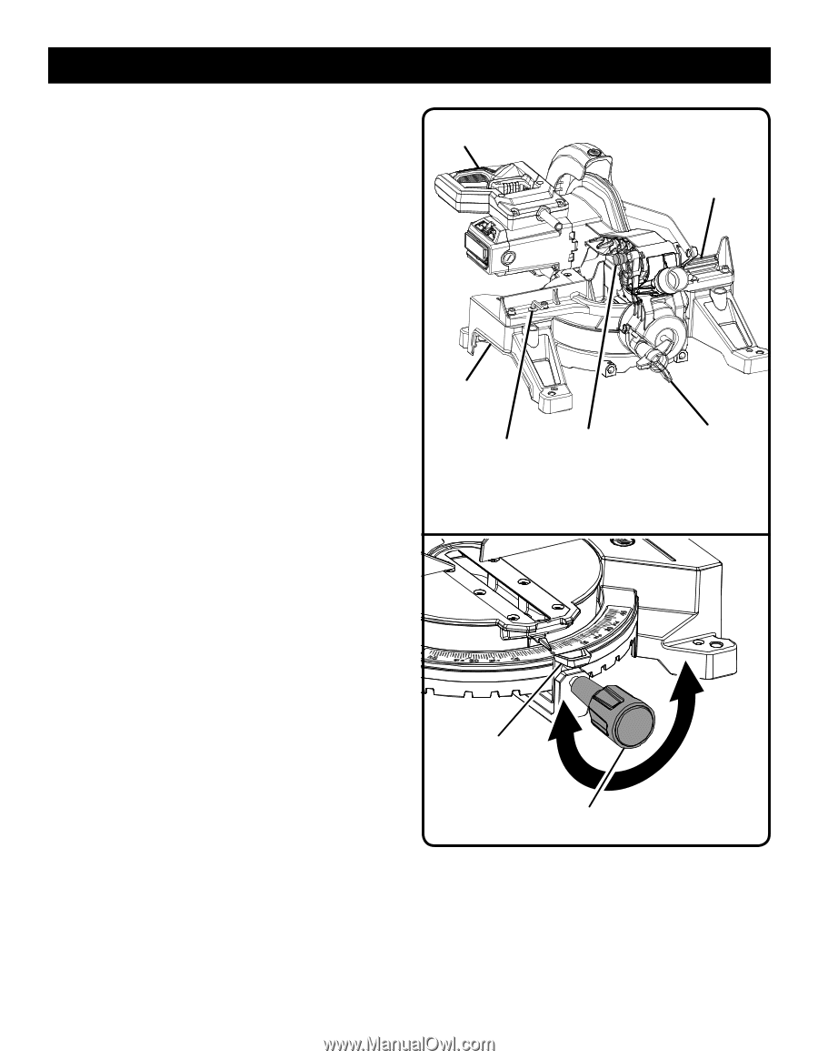
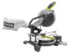
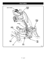
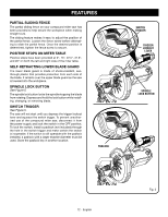
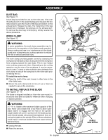
FEATURES KNOW YOUR COMPOUND MITER SAW See Figures 1 - 2. The safe use of this product requires an understanding of the information on the tool and in this operator's manual as well as a knowledge of the project you are attempting. Before use of this product, familiarize yourself with all operating features and safety rules. 7-1/4 in. BLADE A 7-1/4 in. blade is included with the compound miter saw. It will cut materials up to 1-1/2 in. thick or 4-1/4 in. wide, depending upon the angle at which the cut is being made. BEVEL LOCK KNOB See Figure 3. The bevel lock knob securely locks your compound miter saw at desired bevel angles. A positive stop adjustment screw has been provided on each side of the saw arm. These adjustment screws are for making fine adjustments at 0° and 45°. BLADE WRENCH STORAGE A blade wrench is packed with the saw. One end of the wrench is a phillips screwdriver and the other end is a hex key. Use the hex key end when installing or removing blade and the phillips end when removing or loosening screws. A storage area for the blade wrench is located in the saw's base. HANDLE AREA See Figure 3. For convenience when carrying or transporting the miter saw from one place to another, handle areas have been provided on either side of the saw base. To transport, turn off and unplug the saw, securely tighten the slide lock knob, then lower the saw arm and lock it in the down position. Lock saw arm by pushing the lock pin in. NOTE: DO NOT perform any cutting operation with the saw in the locked position. MITER FENCE The miter fence on the compound miter saw has been provided to hold your workpiece securely against when making all cuts. MITER LOCK KNOB See Figure 4. The miter lock knob securely locks the saw at desired miter angles. Turn the miter lock knob clockwise to lock the saw in place. To release the saw, turn the the miter lock knob counterclockwise and depress the detent release button. "D" HANDLE PARTIAL SLIDING FENCE HANDLE AREA BLADE WRENCH LOCK PIN BEVEL LOCK KNOB SAW ARM LOCKED IN DOWN POSITION Fig. 3 DETENT RELEASE BUTTON TO TIGHTEN MITER LOCK KNOB TO LOOSEN Fig. 4 11 - English
-
 1
1 -
2
-
3
-
4
-
5
-
 6
6 -
 7
7 -
 8
8 -
 9
9 -
 10
10 -
 11
11 -
 12
12 -
 13
13 -
 14
14 -
 15
15 -
 16
16 -
17
-
18
-
19
-
20
-
21
-
22
-
23
-
24
-
25
-
26
-
27
-
28
-
29
-
30
-
31
-
32
-
33
-
34
-
35
-
36
-
37
-
38
-
39
-
40
-
41
-
42
-
43
-
44
-
45
-
46
-
47
-
48
-
49
-
50
-
51
-
52
-
53
-
54
-
55
-
56
-
57
-
58
-
59
-
60
-
61
-
62
-
63
-
64
-
65
-
66
-
67
-
68
-
69
-
70
-
71
-
72
-
73
-
74
-
75
-
76
-
77
-
78
-
79
-
80
-
81
-
82
-
83
-
84
-
85
-
86
-
87
-
88
-
89
-
90
-
91
-
92
 |
 |