Ryobi TS1144 Operation Manual - Page 29
Adjustments
 |
View all Ryobi TS1144 manuals
Add to My Manuals
Save this manual to your list of manuals |
Page 29 highlights
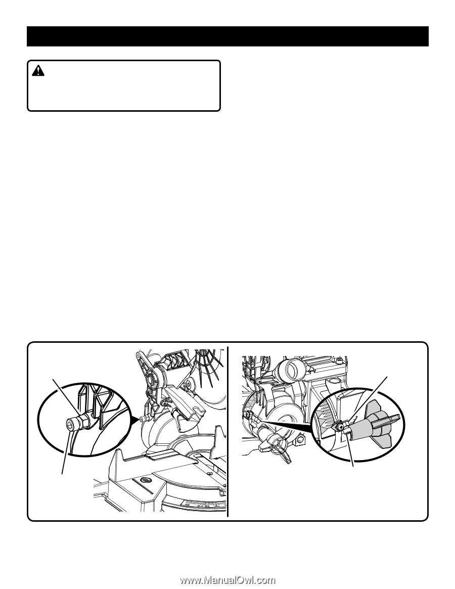
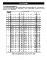
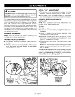
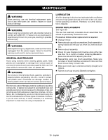
ADJUSTMENTS WARNING: Before performing any adjustment, make sure the tool is unplugged from the power supply. Failure to heed this warning could result in serious personal injury. The compound miter saw has been adjusted at the factory for making accurate cuts. However, some of the components might have been jarred out of alignment during shipping. Also, over a period of time, readjustment will probably become necessary due to wear. After unpacking the saw, check the following adjustments before you begin using the saw. Make any readjustments that are necessary and periodically check the parts alignment to make sure that the saw is cutting accurately. PIVOT ADJUSTMENTS NOTE: These adjustments were made at the factory and normally do not require readjustment. TRAVEL PIVOT ADJUSTMENT The saw arm should rise completely to the up position by itself. If the saw arm does not raise by itself or if there is play in the pivot joints, have saw repaired at your nearest authorized service center. BEVEL PIVOT ADJUSTMENT The compound miter saw should bevel easily by loosening the bevel lock knob and tilting the saw arm to the left. If movement is tight or if there is play in the pivot, have saw repaired by at your nearest authorized service center. POSITIVE STOP ADJUSTMENTS See Figure 34. NOTE: These adjustments were made at the factory and normally do not require readjustment. To adjust: Unplug the saw. Loosen the bevel lock knob by turning the knob counterclockwise. Square the blade to the miter table as described in the Assembly section of this manual. If the blade is out of square, secure the lock nut in place and loosen or tighten the positive stop adjustment screw using the blade wrench provided. Retighten bevel lock knob. Recheck blade-to-table alignment. NOTE: The above procedure can be used to check blade squareness of the saw blade to the miter table at both 0° and 45° angles. The saw has two scale indicators, one on the bevel scale and one on the miter scale. After squaring adjustments have been made, it may be necessary to loosen the indicator screws and reset them to zero. See figures 20 - 21. LOCK NUT LOCK NUT 30 15 0 45 POSITIVE STOP ADJUSTMENT SCREW FOR 0° ANGLES 29 - English POSITIVE STOP ADJUSTMENT SCREW FOR 45° ANGLES Fig. 34
-
 1
1 -
2
-
3
-
4
-
5
-
6
-
7
-
8
-
9
-
10
-
11
-
12
-
13
-
14
-
15
-
16
-
17
-
18
-
19
-
20
-
21
-
22
-
23
-
 24
24 -
 25
25 -
 26
26 -
 27
27 -
 28
28 -
 29
29 -
 30
30 -
 31
31 -
 32
32 -
 33
33 -
 34
34 -
35
-
36
-
37
-
38
-
39
-
40
-
41
-
42
-
43
-
44
-
45
-
46
-
47
-
48
-
49
-
50
-
51
-
52
-
53
-
54
-
55
-
56
-
57
-
58
-
59
-
60
-
61
-
62
-
63
-
64
-
65
-
66
-
67
-
68
-
69
-
70
-
71
-
72
-
73
-
74
-
75
-
76
-
77
-
78
-
79
-
80
-
81
-
82
-
83
-
84
-
85
-
86
-
87
-
88
-
89
-
90
-
91
-
92
 |
 |