Ryobi TS1144 Operation Manual - Page 15
Warning, Mounting Holes, Miter Lock Knob, Locking/unlocking The Saw Arm, Installing The Bevel Lock
 |
View all Ryobi TS1144 manuals
Add to My Manuals
Save this manual to your list of manuals |
Page 15 highlights
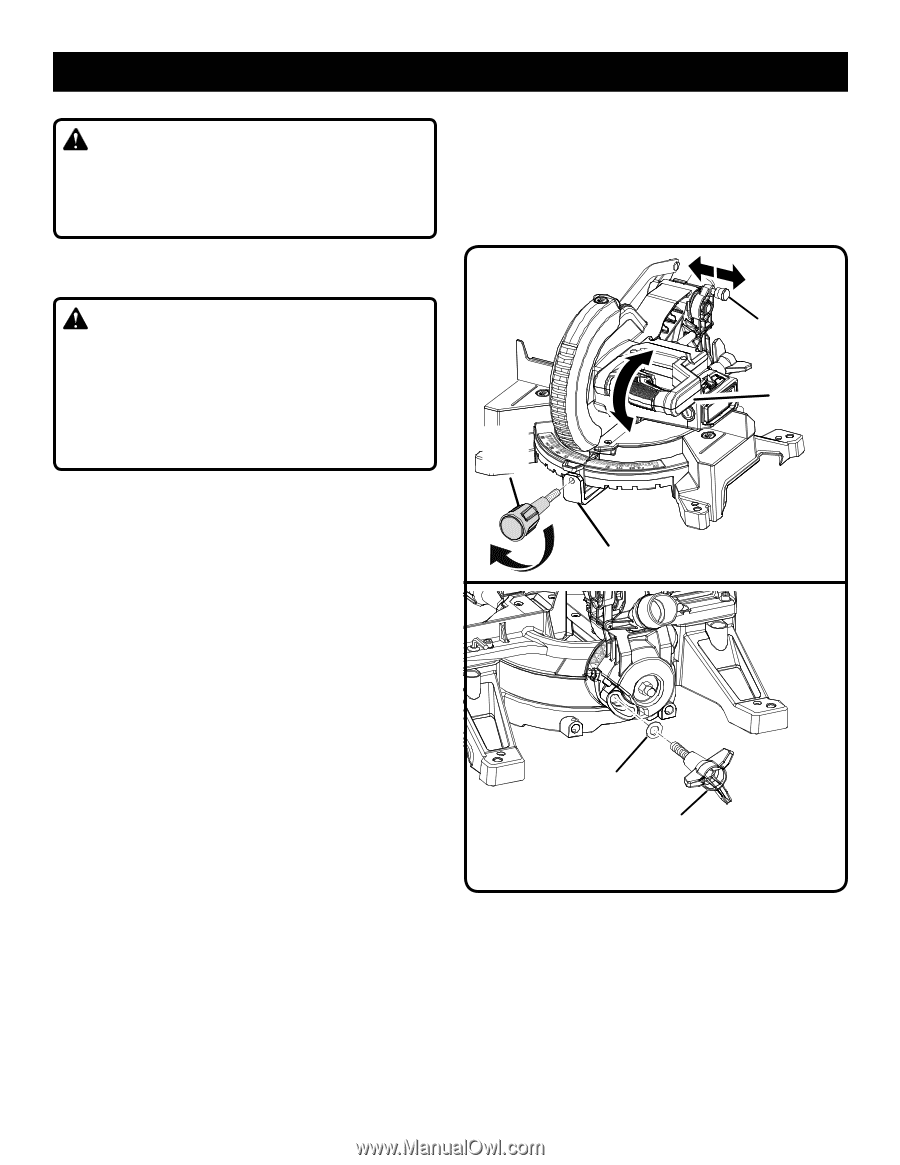
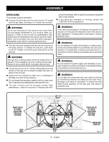
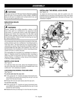
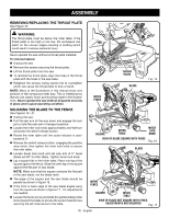
ASSEMBLY WARNING: This saw can tip over if the saw head is released suddenly and the saw is not secured to a work surface. ALWAYS secure this saw to a stable work surface before any use to avoid serious personal injury. INSTALLING THE BEVEL LOCK KNOB See Figure 10. To install the bevel lock knob, slide the washer onto the threaded stud on the end of the bevel lock knob then place the knob into the threaded hole on the back of the saw. Turn clockwise to tighten. MOUNTING HOLES See Figure 8. WARNING: Before starting any cutting operation, clamp or bolt your miter saw to a workbench or an approved miter saw stand. If a miter saw stand is used, read operator's manual and follow the instructions for the miter saw stand. Never operate your miter saw on the floor or in a crouched position. Failure to heed this warning can result in serious personal injury. The compound miter saw should be mounted to a firm supporting surface such as a workbench, mounting board, or miter saw stand. The saw base has four mounting holes. If using bolts or screws, they should be of sufficient length to accommodate the saw base, lock washers, hex nuts, and the thickness of the workbench or other mounting surface. Tighten all bolts or screws securely. The hole pattern for mounting to a workbench is shown in figure 8. Carefully check the workbench after mounting to make sure that no movement can occur during use. If any tipping, sliding, or walking is noted, secure the workbench to the floor before operating. MITER LOCK KNOB See Figure 9. To install the miter lock knob, place the threaded stud on the end of the miter lock knob into the threaded hole in the control arm. Turn clockwise to tighten. LOCKING/UNLOCKING THE SAW ARM See Figure 9. To unlock and raise the saw arm: Firmly grasp the "D" handle and apply downward pressure while at the same time pulling the lock pin out and away from the saw housing. Release the lock pin and slowly raise the saw arm. To lock the saw arm: Firmly grasp the "D" handle and apply downward pressure while at the same time pushing the lock pin in and toward the saw housing. Release the lock pin allowing it to lock the saw into place. MITER LOCK KNOB CONTROL ARM WASHER BEVEL LOCK KNOB LOCK PIN "D" HANDLE Fig. 9 Fig. 10 15 - English
-
 1
1 -
2
-
3
-
4
-
5
-
6
-
7
-
8
-
9
-
 10
10 -
 11
11 -
 12
12 -
 13
13 -
 14
14 -
 15
15 -
 16
16 -
 17
17 -
 18
18 -
 19
19 -
 20
20 -
21
-
22
-
23
-
24
-
25
-
26
-
27
-
28
-
29
-
30
-
31
-
32
-
33
-
34
-
35
-
36
-
37
-
38
-
39
-
40
-
41
-
42
-
43
-
44
-
45
-
46
-
47
-
48
-
49
-
50
-
51
-
52
-
53
-
54
-
55
-
56
-
57
-
58
-
59
-
60
-
61
-
62
-
63
-
64
-
65
-
66
-
67
-
68
-
69
-
70
-
71
-
72
-
73
-
74
-
75
-
76
-
77
-
78
-
79
-
80
-
81
-
82
-
83
-
84
-
85
-
86
-
87
-
88
-
89
-
90
-
91
-
92
 |
 |