Ryobi TS1343L Operation Manual - Page 10
Know Your Compound Miter Saw, Amp Motor, In. Blade, Bevel Lock Knob, Blade Wrench Storage, D Handle - 10 compound miter saw with laser
 |
View all Ryobi TS1343L manuals
Add to My Manuals
Save this manual to your list of manuals |
Page 10 highlights
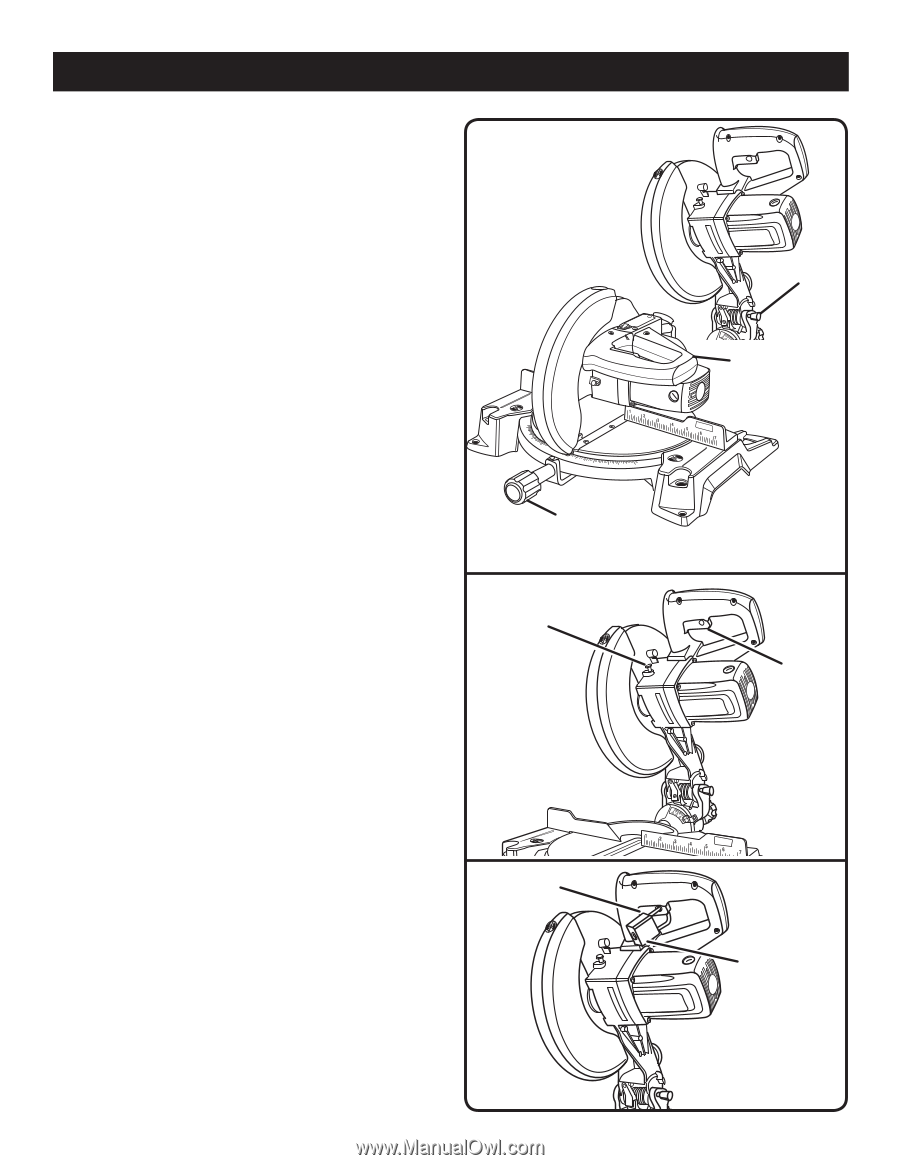
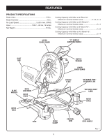
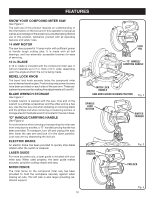
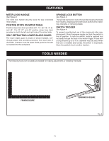
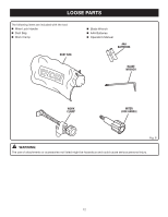
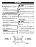
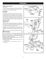
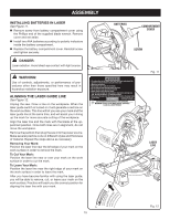
FEATURES KNOW YOUR COMPOUND MITER SAW See Figure 1. The safe use of this product requires an understanding of the information on the tool and in this operator's manual as well as a knowledge of the project you are attempting. Before use of this product, familiarize yourself with all operating features and safety rules. 14 AMP MOTOR The saw has a powerful 14 amp motor with sufficient power to handle tough cutting jobs. It is made with all ball bearings, and has externally accessible brushes for ease of servicing. 10 in. BLADE A 10 in. blade is included with the compound miter saw. It will cut materials up to 2 in. thick or 6 in. wide, depending upon the angle at which the cut is being made. BEVEL LOCK KNOB The bevel lock knob securely locks the compound miter saw at desired bevel angles. Positive stop adjustment screws have been provided on each side of the saw arm. These adjustment screws are for making fine adjustments at 0° and 45°. BLADE WRENCH STORAGE See Figure 1. A blade wrench is packed with the saw. One end of the wrench is a phillips screwdriver and the other end is a hex key. Use the hex key end when installing or removing blade and the phillips end when removing or loosening screws. A storage area for the blade wrench is located in the saw's base. "D" HANDLE/CARRYING HANDLE See Figure 2. For convenience when carrying or transporting the miter saw from one place to another, a "D" handle/carrying handle has been provided. To transport, turn off and unplug the saw, then lower the saw arm and lock it in the down position. Lock saw arm by depressing the lock pin. ELECTRIC BRAKE An electric brake has been provided to quickly stop blade rotation after the switch is released. LASER GUIDE For more accurate cuts, a laser guide is included with your miter saw. When used properly, the laser guide makes accurate, precision cutting simple and easy. MITER FENCE The miter fence on the compound miter saw has been provided to hold the workpiece securely against when making all cuts. The left side is also larger providing additional support. 10 LOCK PIN "D" HANDLE/ CARRYING HANDLE MITER LOCK HANDLE SAW ARM LOCKED IN DOWN POSITION Fig. 2 SPINDLE LOCK BUTTON SWITCH TRIGGER SWITCH TRIGGER Fig. 3 PADLOCK Fig. 4
-
 1
1 -
2
-
3
-
4
-
 5
5 -
 6
6 -
 7
7 -
 8
8 -
 9
9 -
 10
10 -
 11
11 -
 12
12 -
 13
13 -
 14
14 -
 15
15 -
16
-
17
-
18
-
19
-
20
-
21
-
22
-
23
-
24
-
25
-
26
-
27
-
28
-
29
-
30
 |
 |