Ryobi TS1343L Operation Manual - Page 17
Warning, Squaring The Miter Table To The Fence
 |
View all Ryobi TS1343L manuals
Add to My Manuals
Save this manual to your list of manuals |
Page 17 highlights
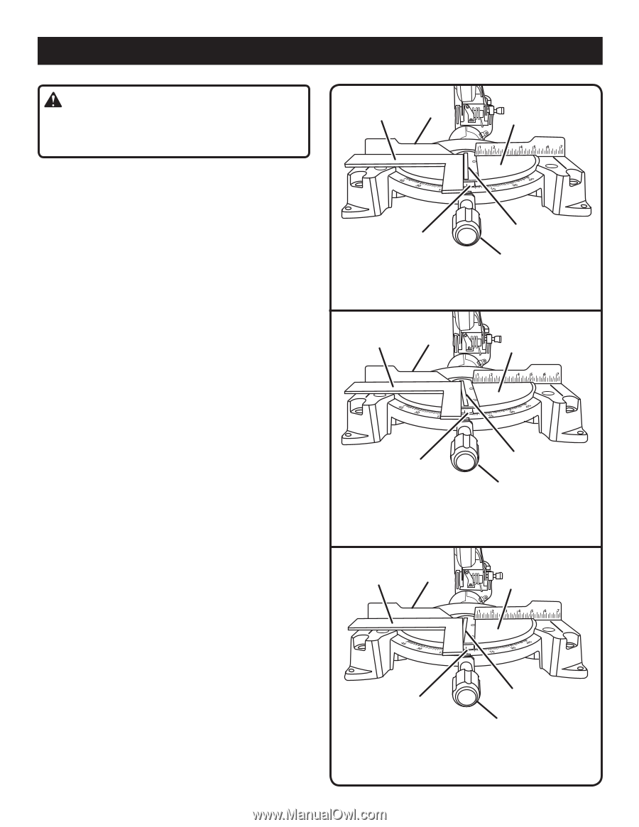
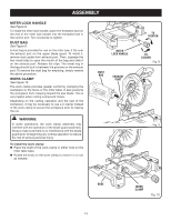
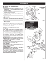
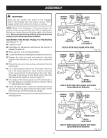
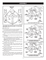
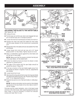
ASSEMBLY WARNING: Make sure the spindle lock button is not engaged before reconnecting saw into power source. Never engage spindle lock button when blade is rotating. NOTE: Many of the illustrations in this manual show only portions of the compound miter saw. This is intentional so that we can clearly show points being made in the illustrations. Never operate the saw without all guards securely in place and in good operating condition. SQUARING THE MITER TABLE TO THE FENCE See Figures 15 - 18. Unplug the saw. Push down on the saw arm and pull out the lock pin to release the saw arm. Raise saw arm to its full raised position. Loosen the miter lock handle approximately one-half turn. Depress the miter lock plate and rotate the miter table until the scale indicator on the control arm is positioned at 0°. Release the miter lock plate and securely tighten the miter lock handle. Lay a framing square flat on the miter table. Place one leg of the square against the fence. Place the other leg of the square beside the throat plate in the miter table. The edge of the square and the throat plate in the miter table should be parallel as shown in figure 15. If the edge of the framing square and the throat plate in the miter table are not parallel as shown in figures 16 and 17, adjustments are needed. Using the blade wrench, loosen the socket head screws securing the fence. Adjust the fence left or right until the framing square and throat plate are parallel. Retighten the screws securely and recheck the fence-totable alignment. FRAMING SQUARE MITER FENCE MITER TABLE SCALE INDICATOR THROAT PLATE MITER LOCK HANDLE VIEW OF MITER TABLE SQUARE WITH FENCE Fig. 15 FRAMING MITER SQUARE FENCE MITER TABLE SCALE INDICATOR THROAT PLATE MITER LOCK HANDLE VIEW OF MITER TABLE NOT SQUARE WITH FENCE, ADJUSTMENTS ARE REQUIRED Fig. 16 FRAMING MITER SQUARE FENCE MITER TABLE SCALE INDICATOR THROAT PLATE MITER LOCK HANDLE VIEW OF MITER TABLE NOT SQUARE WITH FENCE, ADJUSTMENTS ARE REQUIRED Fig. 17 17
-
 1
1 -
2
-
3
-
4
-
5
-
6
-
7
-
8
-
9
-
10
-
11
-
 12
12 -
 13
13 -
 14
14 -
 15
15 -
 16
16 -
 17
17 -
 18
18 -
 19
19 -
 20
20 -
 21
21 -
 22
22 -
23
-
24
-
25
-
26
-
27
-
28
-
29
-
30
 |
 |