Ryobi TS1343L Operation Manual - Page 11
Features, Tools Needed - blade guard
 |
View all Ryobi TS1343L manuals
Add to My Manuals
Save this manual to your list of manuals |
Page 11 highlights
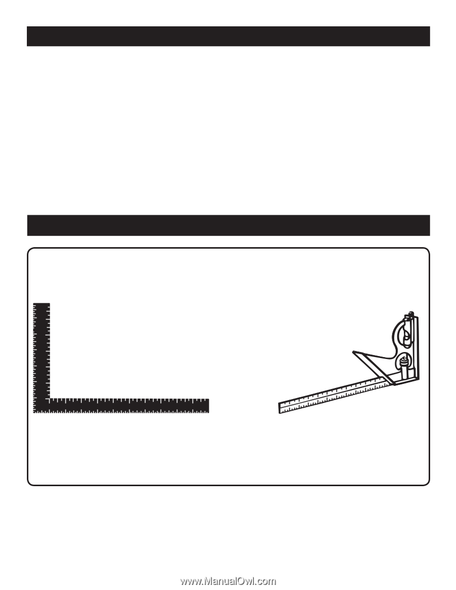
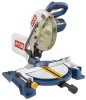
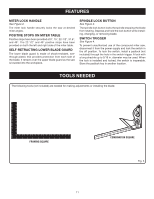
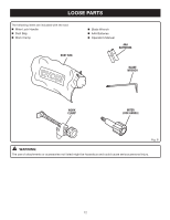
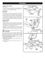
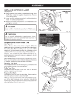
FEATURES MITER LOCK HANDLE See Figure 2. The miter lock handle securely locks the saw at desired miter angles. POSITIVE STOPS ON MITER TABLE Positive stops have been provided at 0°, 15°, 22-1/2°, 31.6°, and 45°. The 22-1/2° and 45° positive stops have been provided on both the left and right side of the miter table. SELF-RETRACTING LOWER BLADE GUARD The lower blade guard is made of shock-resistant, seethrough plastic that provides protection from each side of the blade. It retracts over the upper blade guard as the saw is lowered into the workpiece. SPINDLE LOCK BUTTON See Figure 3. The spindle lock button locks the spindle stopping the blade from rotating. Depress and hold the lock button while installing, changing, or removing blade. SWITCH TRIGGER See Figure 4. To prevent unauthorized use of the compound miter saw, disconnect it from the power supply and lock the switch in the off position. To lock the switch, install a padlock (not included) through the hole in the switch trigger. A lock with a long shackle up to 5/16 in. diameter may be used. When the lock is installed and locked, the switch is inoperable. Store the padlock key in another location. TOOLS NEEDED The following tools (not included) are needed for making adjustments or installing the blade: FRAMING SQUARE 11 COMBINATION SQUARE Fig. 5
-
 1
1 -
2
-
3
-
4
-
5
-
 6
6 -
 7
7 -
 8
8 -
 9
9 -
 10
10 -
 11
11 -
 12
12 -
 13
13 -
 14
14 -
 15
15 -
 16
16 -
17
-
18
-
19
-
20
-
21
-
22
-
23
-
24
-
25
-
26
-
27
-
28
-
29
-
30
 |
 |