Samsung 2220WM Service Manual - Page 43
IP Board PartPower Schematic Diagrams, Power, Switching Mode Power Supply - capacitor
 |
UPC - 729507801940
View all Samsung 2220WM manuals
Add to My Manuals
Save this manual to your list of manuals |
Page 43 highlights
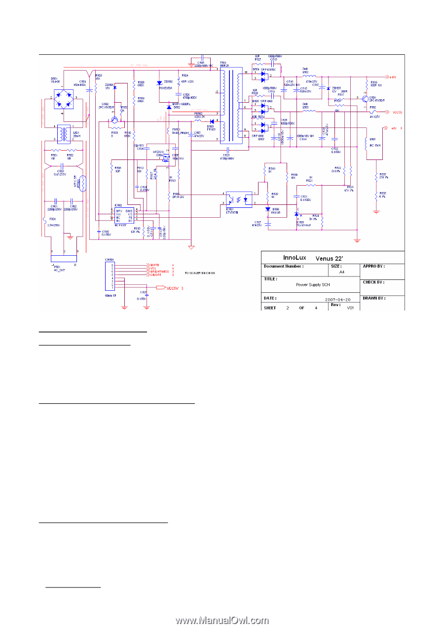
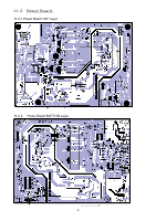
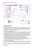
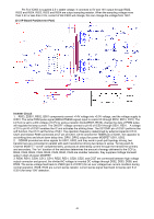
12-2 IP Board Part(Power) Schematic Diagrams Power Switching Mode Power Supply 1.1 AC Current Input Circuit P801 is a connector for connecting AC Power. F801 is a fuse to protect all the circuit. AC input voltage is from 90v to 264V. R801 and R802 joined between two inputting main circuit to prevent man from shock. L801 is used to clear up low frequency wave. C801 and C802 are used to discharge the waves that L801 produced. High frequency waves are damped by C801 and C802. D801 is a rectifier which composed of 4 build-in diodes, it inverts AC to DC. 1.2 High Voltage to Low Voltage Control Circuit C804 is used to smooth the wave from rectifier. IC802 is a highly integrated PWM controller. When rectified DC high voltage is applied to the HV pin during start-up, the MOSFET Q804 is initially off, and the Vcc pin capacitor is charged. When the Vcc pin voltage reaches approximately 10V, the control circuitry is activated and the soft-start begins. The soft-start circuit gradually increases the duty cycle of the MOSFET from zero to the maximum value over approximately 4ms. If no external feedback/supply current is fed into the FB pin by the end of the soft-start, the current Setpoint will be above the fault level, FAULT flag is raised, if the FAULT duration exceeds 80ms, the output controller disable Resistor R808, R809, R810, R811 are for line over voltage shutdown(OVP) When PWM is turned off, the main current flow will be consumed through R804 and D802, This will prevent MOSFET Q804 from being damaged under large current impulse and voltage spike. D803 and C807 to provide internal Auxiliary voltage to Vcc pin during normal operation. Otherwise, error amplifier and feedback current input the FB pin for duty cycle control. 1.3 DC_5V and DC_14V Output Circuit For DC 5V, D805 is used to rectify the inducted current. R828 and C814 are used to store energy when current is reversed. The parts including C818, C822, C820,L803 are used to smooth the current waves. For DC 14V, D803 is used to rectify the inducted current. R827 and C813 are used to store energy when current is reversed. The parts including C815, C817 and L802 are used to smooth the current waves. 3.1.4 Feedback 44
-
 1
1 -
2
-
3
-
4
-
5
-
6
-
7
-
8
-
9
-
10
-
11
-
12
-
13
-
14
-
15
-
16
-
17
-
18
-
19
-
20
-
21
-
22
-
23
-
24
-
25
-
26
-
27
-
28
-
29
-
30
-
31
-
32
-
33
-
34
-
35
-
36
-
37
-
 38
38 -
 39
39 -
 40
40 -
 41
41 -
 42
42 -
 43
43 -
 44
44 -
 45
45 -
 46
46 -
 47
47 -
 48
48 -
49
 |
 |