Samsung RB215BSSB Service Manual - Page 53
MODEL OPTION CIRCUIT, 10 Buzzer Circuit Diagram
 |
View all Samsung RB215BSSB manuals
Add to My Manuals
Save this manual to your list of manuals |
Page 53 highlights
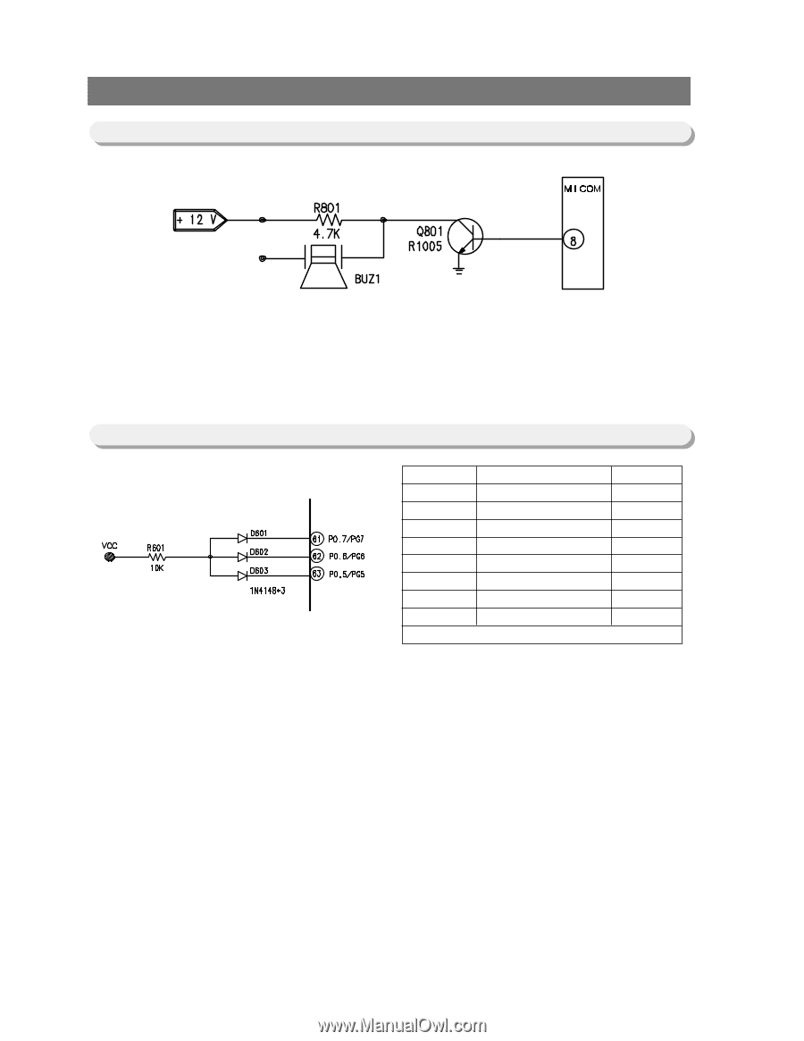
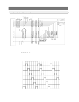
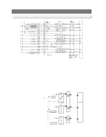
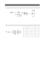
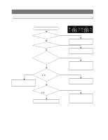
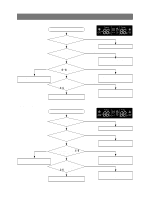
OPERATION PRINCIPLES BY PARTS OF CIRCUIT 12-10) Buzzer Circuit Diagram 1) The circuit is composed of like the above and MICOM controls the alarm function with 2KHz.12V is always applied to the circuit.So,when MICOM sends alarm signals to Q801 Transistor Bass,the transistor is turned on applying 12V to the buzzer,which operates the buzzer. 4.7Kohm of R801 is a resistance for the production of quality buzzer sound. 12-11) MODEL OPTION CIRCUIT D601 ICE MAKER OPRION X • D602 USE NOT USE TEMP.OPTION X ℉ • ℃ D603 X • •* Diode(1N4148)USE REMARKS REMARKS REMARKS 1) This circuit operates with the initial power on and uses DIODE (1N4148). To modify the option circuit,the power should be turned off before being modified and turned on after the modification. Refer to the table above,the default factory values are highly recommended unless exceptional cases. 53
-
 1
1 -
2
-
3
-
4
-
5
-
6
-
7
-
8
-
9
-
10
-
11
-
12
-
13
-
14
-
15
-
16
-
17
-
18
-
19
-
20
-
21
-
22
-
23
-
24
-
25
-
26
-
27
-
28
-
29
-
30
-
31
-
32
-
33
-
34
-
35
-
36
-
37
-
38
-
39
-
40
-
41
-
42
-
43
-
44
-
45
-
46
-
47
-
 48
48 -
 49
49 -
 50
50 -
 51
51 -
 52
52 -
 53
53 -
 54
54 -
 55
55 -
 56
56 -
 57
57 -
 58
58 -
59
-
60
-
61
-
62
-
63
-
64
-
65
-
66
-
67
-
68
-
69
-
70
-
71
-
72
-
73
-
74
-
75
-
76
-
77
-
78
-
79
-
80
 |
 |