Samsung SCC-B2300 Service Manual - Page 12
Alignment and Adjustment - camera
 |
View all Samsung SCC-B2300 manuals
Add to My Manuals
Save this manual to your list of manuals |
Page 12 highlights
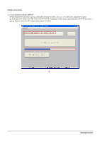
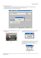
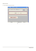
3. Alignment and Adjustment 3-1 Ca le Connection and Preparation(Data adjustment) 3-1-1 Ca le Connection MONITOR PC RS232/RS485 Jig Board RS232C Cable 4-Pin Cable Fig. 3-1 Connection Diagram Connect the CAMERA , RS-232/485 Jig and the Computer as shown above. - 4 Pin Cable : This cable is a connection cable which connects the 4pin connector of the camera and the adjustment jig. - RS232C Cable : This cable is a connection cable of an adjustment jig and PC.(* Use COM1) - RS232/RS485 Jig Board : This is the adjustment Jig Board. Select the RS-232. - Before starting the adjustment process, OFF the Switch ! (L/L Switch) on the Rear board. Camera I Port T Camea Side Camera Side round ig. Samsung Electronics 3-1
-
 1
1 -
2
-
3
-
4
-
5
-
6
-
 7
7 -
 8
8 -
 9
9 -
 10
10 -
 11
11 -
 12
12 -
 13
13 -
 14
14 -
 15
15 -
 16
16 -
 17
17 -
18
-
19
-
20
-
21
-
22
-
23
-
24
-
25
-
26
-
27
-
28
-
29
-
30
-
31
-
32
-
33
-
34
-
35
-
36
-
37
-
38
-
39
-
40
-
41
-
42
-
43
-
44
-
45
-
46
-
47
-
48
-
49
-
50
-
51
-
52
-
53
-
54
-
55
-
56
-
57
-
58
-
59
-
60
-
61
-
62
-
63
-
64
-
65
-
66
-
67
-
68
-
69
-
70
-
71
-
72
-
73
-
74
-
75
-
76
-
77
-
78
-
79
-
80
-
81
-
82
-
83
-
84
-
85
-
86
-
87
 |
 |

Samsung Electronics
3-1
Fig. 3-1 Connection Diagram
3. Alignment and Adjustment
3-1 Ca le Connection and Preparation(Data adjustment)
3-1-1 Ca le Connection
MONITOR
PC
RS232/RS485
Jig Board
RS232C
Cable
4-Pin
Cable
Connect the CAMERA , RS-232/485 Jig and the Computer as shown above.
- 4 Pin Cable : This cable is a connection cable which connects the 4pin connector of the camera and
the adjustment jig.
- RS232C Cable : This cable is a connection cable of an adjustment jig and PC.(* Use COM1)
- RS232/RS485 Jig Board : This is the adjustment Jig Board. Select the RS-232.
- Before starting the adjustment process, OFF the Switch
!
(L/L Switch) on the Rear board.
ig.
Camera
I
Port
T
Camea Side
Camera Side
round