Samsung TL500 User Manual (user Manual) (ver.1.0) (English) - Page 16
Camera layout
 |
UPC - 044701012993
View all Samsung TL500 manuals
Add to My Manuals
Save this manual to your list of manuals |
Page 16 highlights
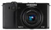
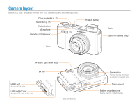
Camera layout Before you start, familiarize yourself with your camera's parts and their functions. Drive mode dial (p. 17) Mode dial (p. 17) Shutter button Microphone Remote control sensor POWER button Flash Eyelet for camera strap Lens AF-assist light/Timer lamp EV dial HDMI port Accepts HDMI cable USB and A/V port Accepts USB cable or A/V cable Basic functions 15 Camera ring Remove the ring and mount an optional conversion lens Tripod mount Battery chamber cover Insert a memory card and battery
-
 1
1 -
2
-
3
-
4
-
5
-
6
-
7
-
8
-
9
-
10
-
 11
11 -
 12
12 -
 13
13 -
 14
14 -
 15
15 -
 16
16 -
 17
17 -
 18
18 -
 19
19 -
 20
20 -
 21
21 -
22
-
23
-
24
-
25
-
26
-
27
-
28
-
29
-
30
-
31
-
32
-
33
-
34
-
35
-
36
-
37
-
38
-
39
-
40
-
41
-
42
-
43
-
44
-
45
-
46
-
47
-
48
-
49
-
50
-
51
-
52
-
53
-
54
-
55
-
56
-
57
-
58
-
59
-
60
-
61
-
62
-
63
-
64
-
65
-
66
-
67
-
68
-
69
-
70
-
71
-
72
-
73
-
74
-
75
-
76
-
77
-
78
-
79
-
80
-
81
-
82
-
83
-
84
-
85
-
86
-
87
-
88
-
89
-
90
-
91
-
92
-
93
-
94
-
95
-
96
-
97
-
98
-
99
-
100
-
101
-
102
-
103
-
104
-
105
-
106
-
107
-
108
-
109
-
110
-
111
-
112
-
113
-
114
-
115
-
116
-
117
-
118
-
119
-
120
-
121
-
122
-
123
-
124
-
125
-
126
-
127
-
128
-
129
 |
 |

Basic functions
15
Camera layout
Before you start, familiarize yourself with your camera's parts and their functions.
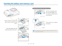
Battery chamber cover
Insert a memory card and battery
Tripod mount
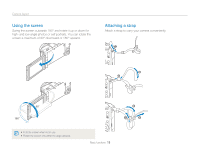
Camera ring
Remove the ring and mount
an optional conversion lens
AF-assist light/Timer lamp
EV dial
POWER button
Remote control sensor
Flash
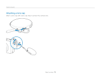
Eyelet for camera strap
Lens
Shutter button
Microphone
Mode dial
(p. 17)
Drive mode dial
(p. 17)
HDMI port
Accepts HDMI cable
USB and A/V port
Accepts USB cable or A/V cable