Samsung TXJ2766 Service Manual - Page 16
Temporarily short Pin R and Pin X on - digital
 |
View all Samsung TXJ2766 manuals
Add to My Manuals
Save this manual to your list of manuals |
Page 16 highlights
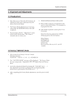
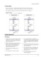
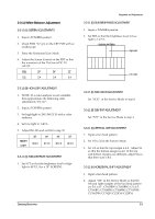
Alignment and Adjustments 3-3-2 Automatic Degaussing A degaussing coil is mounted around the picture tube, so external degaussing after moving the TV should be unnecessary. However, the receiver must be properly degaussed upon installation. The degaussing coil operates for about 1 second after the power is switched ON. If the set has been moved or turned in a different direction, disconnect its AC power for at least 10 Minutes. If the chassis or parts of the cabinet become magnetized, poor color purity will result. If this happens, use an external degaussing coil. Slowly move the degaussing coil around the faceplate of the picture tube and the sides and front of the receiver. Slowly withdraw the coil to a distance of about 6 feet before removing power. 3-3-3 High Voltage Check CAUTION : There is no high voltage adjustment on this chassis. The B+ power supply must be set to either +135V or +125V (for 20Ó screen). Conditions : Full color bar input and normal picture level. 1. Connect a digital voltmeter to the second anode of the picture tube. 2. Turn on the TV. Set the Brightness and Contrast controls to minimum (zero beam current). 3. The high voltage must not exceed 29.5KV. 4. Adjust the Brightness and Contrast controls to both extremes. Ensure that the high voltage does not exceed 29.5KV under any conditions. SIZE MAX H-VOLTAGE 21"± 1 27.5KV 25" 29.5KV 29" 29.5KV 29"± 1 29.5KV 3-3-4 FOCUS Adjustment 1. Input a black and white signal. 2. Adjust the tuning control for the clearest picture. 3. Adjust the FOCUS control for well defined scanning lines in the center area of the screen. 3-3-5 B+ Line Check There are 3 power modes : 1. ÒAÓ : When AC power supply is connected ; Ò Stand-ByÓ mode. 2. ÒBÓ : When Ò Set Power-ONÓ button is pressed. 3. ÒCÓ : Driven by FBT. Each voltage is marked on its lead-in wire. ( ) 3-3-6 F/S (Fail Safe) Circuit Check 1. The failsafe circuit check is the final step after servicing. 2. Turn the power switch on and adjust the screen for ÒNormalÓ. 3. Temporarily short Pin R and Pin X on the chassis (RX05, RX04). Sound and picture will disappear. 4. The TV should remain in this state. This shows that the failsafe circuit is working properly. 5. To restore picture and sound, temporarily turn off the AC power supply. After about 30 seconds, switch power ON. 3-6 Samsung Electronics
-
 1
1 -
2
-
3
-
4
-
5
-
6
-
7
-
8
-
9
-
10
-
 11
11 -
 12
12 -
 13
13 -
 14
14 -
 15
15 -
 16
16 -
 17
17 -
 18
18 -
 19
19 -
 20
20 -
 21
21 -
22
-
23
-
24
-
25
-
26
-
27
-
28
-
29
-
30
-
31
-
32
-
33
-
34
-
35
-
36
-
37
-
38
-
39
-
40
-
41
-
42
-
43
-
44
-
45
-
46
-
47
-
48
-
49
-
50
-
51
-
52
-
53
-
54
-
55
-
56
-
57
-
58
-
59
-
60
-
61
-
62
-
63
-
64
-
65
-
66
-
67
-
68
 |
 |
