Samsung TXJ2766 Service Manual - Page 20
Precautions when servicing, 3-12 Power Consumption Reduction, Circuit during Stand-by Option
 |
View all Samsung TXJ2766 manuals
Add to My Manuals
Save this manual to your list of manuals |
Page 20 highlights
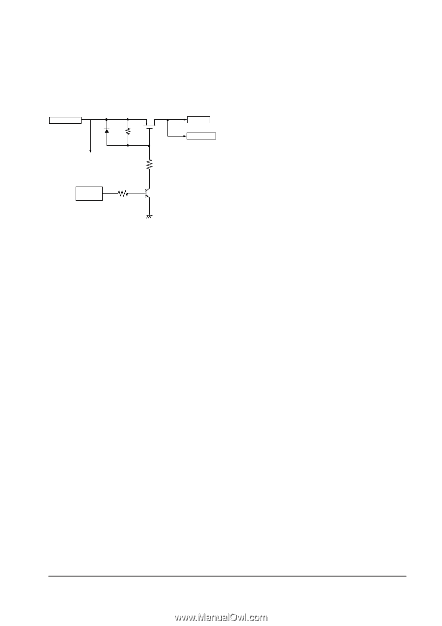
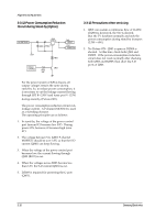
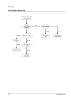
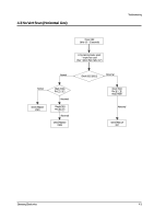
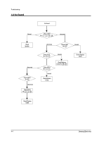
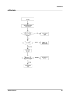
Alignment and Adjustments 3-3-12 Power Consumption Reduction Circuit during Stand-by (Option) 130 RECTIFIED Q801 SFP9640 DZ809 R812 OmA R801 OmA FBT B+ OmA TUNER 33V POWER CONTROL R910 10K Q903 3-3-13 Precautions when servicing 1. Q801 can sustain a continuous flow of 11ADC. If Q801 is destroyed, the S-D is shorted. But, the TV functions normally and only the power consumption during stand-by increases (2.5W® 6W). 2. No Picture ON : Q903 is open or DZ809 is shorted. At this time, check both Q903 and DZ809. If the power-consumption reduction circuit does not work normally after checking both Q903 and DZ809, then short the S-D ports of Q801. For the power system of K51A chassis, all output voltages remain the same during stand-by. So, to reduce power consumption, it is necessary to cut the leakage current flowing through FBT B+ (130V) and tuner port VT (33V) during stand-by (Picture OFF). The power consumption reduction circuit cuts leakage current. A P-channel MOSFET is used as a switching element. The operating principles are as follows: 1. In stand-by, the voltage of the power control port (micom IC) becomes low (0V). During power ON, however, it becomes high (over 4V). 2. The voltage between S-G (Q801 P-channel MOSFET) should be over 3.5V, so that the S-D current (Q801) can keep flowing. 3. When the voltage of the power control port becomes low, the current flowing through Q903 (R812) is cut. 4. When the voltages across R803 become less than 3.5V, the S-D current (Q801) is cut. 5. DZ809 is required for protecting the G-port (Q801). 3-10 Samsung Electronics
-
 1
1 -
2
-
3
-
4
-
5
-
6
-
7
-
8
-
9
-
10
-
11
-
12
-
13
-
14
-
 15
15 -
 16
16 -
 17
17 -
 18
18 -
 19
19 -
 20
20 -
 21
21 -
 22
22 -
 23
23 -
 24
24 -
 25
25 -
26
-
27
-
28
-
29
-
30
-
31
-
32
-
33
-
34
-
35
-
36
-
37
-
38
-
39
-
40
-
41
-
42
-
43
-
44
-
45
-
46
-
47
-
48
-
49
-
50
-
51
-
52
-
53
-
54
-
55
-
56
-
57
-
58
-
59
-
60
-
61
-
62
-
63
-
64
-
65
-
66
-
67
-
68
 |
 |