SanDisk 4GB micro SDHC Memory Card for Product Manual - Page 22
General Description, SD Bus Protocol, Functional Description - reset
 |
UPC - 084331428832
View all SanDisk 4GB micro SDHC Memory Card for manuals
Add to My Manuals
Save this manual to your list of manuals |
Page 22 highlights
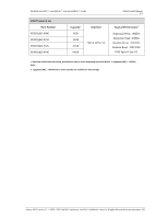
SanDisk microSD™, microSDHC™ and microSDXC™ cards OEM Product Manual 2.5 Table 10: Minimum User Area DOS Image Parameters Capacity1 Total LBAs2 No. of Partition System Area Sectors2 Total Partition Sectors2 User Data Sectors2 User Data Bytes2 64 GB 32GB 16 GB 8 GB 125,000,704 62,333,952 31,116,288 15,523,840 66304 16384 8192 8192 124,967,936 62,325,760 31,108,096 15,515,648 124,934,400 62,309,376 31,099,904 15,507,456 63,864,569,856 31,902,400,512 15,923,150,848 7,939,817,472 4 GB 7,744,512 8192 7,736,320 7,728,128 3,956,801,536 2 GB 3,862,528 505 3,858,489 3,857,984 1,975,287,808 1 GB 1,930,240 505 1,929,177 1,928,672 987,480,064 1 1 (GB) = 1billion bytes. Some capacity not available for data storage. 2 Total LBAs, Number of Partition System Area Sectors, Total Partition Sectors, User Data Sectors and User Data Bytes are minimum values. Actual values may vary depending on flash technology used. 4 MICROSD CARD PROTOCOL DESCRIPTION 4.1 General Description SD™ Protocol information for cards in the SanDisk microSD™ Card Product Family is contained in this chapter; information includes SD bus protocol, card identification, and a functional description. 4.2 SD Bus Protocol Communication over the SD bus is based on command and data-bit streams initiated by a start bit and terminated by a stop bit. See Section 3.6.1 of the SDA Physical Layer Specification, Version 3.01 for details. 4.3 Functional Description In the SanDisk microSD Card Product Family, the host controls all communication between itself and the cards. This section provides a general overview of the card identification and data transfer modes; commands; card dependencies; various card operation modes and restrictions for controlling the clock signal. For SD Card commands, together with corresponding responses, state transitions, error conditions, and timings refer to Section 4 of the SDA Physical Layer Specification, Version 3.01. 4.3.1 Card Identification Mode In Card Identification Mode, the host resets all cards, validates operation voltage range, identifies and requests cards to publish a relative card address. For more information see Section 4.2 in the SDA Physical Layer Specification, Version 3.01. 4.3.2 Data Transfer Mode Functionality of the Data Transfer Mode can be found in Section 4.3 of the SDA Physical Layer Specification, Version 3.01. This section includes information about data read and write, erase, write-protect management, card lock/unlock operations, application-specific commands, switch function command, high-speed mode, command system, and the Send Interface Condition command (CMD8). CMD8 is part of identification mode and command functional differences in microSD cards. January 2012 Version 2.5 © 2008 - 2012 SanDisk Corporation. SanDisk Confidential, subject to all applicable non-disclosure agreements 17
-
 1
1 -
2
-
3
-
4
-
5
-
6
-
7
-
8
-
9
-
10
-
11
-
12
-
13
-
14
-
15
-
16
-
 17
17 -
 18
18 -
 19
19 -
 20
20 -
 21
21 -
 22
22 -
 23
23 -
 24
24 -
 25
25 -
 26
26
 |
 |
