Sanyo CE42LM4WPN-NA Owner's Manual for POA-LN01 - Page 9
LCD Monitor, Network Board, Monitor - parts
 |
UPC - 086483065156
View all Sanyo CE42LM4WPN-NA manuals
Add to My Manuals
Save this manual to your list of manuals |
Page 9 highlights
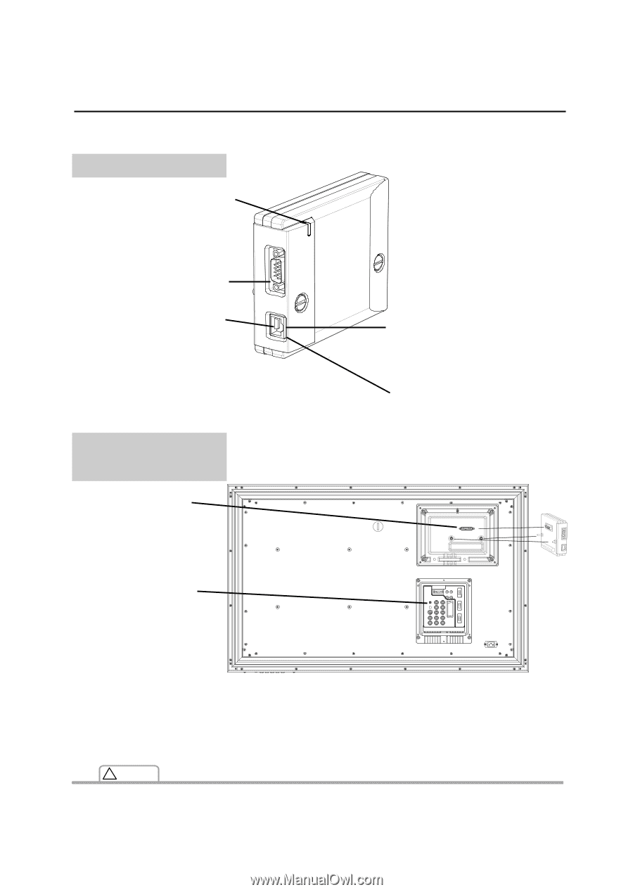
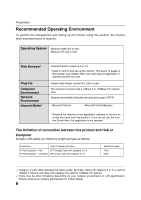
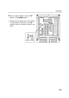
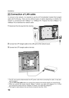
Name and function of each part Network Board Power indicator This illuminates red when the network board is mounted onto the monitor and the AC plug is connected . Serial port Connecting the Serial cable. LAN port Connecting the LAN cable. Monitor (Rear Terminal of Monitor) Input port Connecting the output connection from the network board. Name and function of each part LINK indicator (Orange) This illuminates orange when the network board is connected to the network correctly. ACT indicator (Green) This turns on and off when sending or receiving of data Option Switch Set to the down position for the network board use. ✐ Set back to the UP position when the network board is not used. (LCD) Monitor ! Caution ✐ Do not touch the connector. It may damage the product. 9
-
 1
1 -
2
-
3
-
 4
4 -
 5
5 -
 6
6 -
 7
7 -
 8
8 -
 9
9 -
 10
10 -
 11
11 -
 12
12 -
 13
13 -
 14
14 -
15
-
16
-
17
-
18
-
19
-
20
-
21
-
22
-
23
-
24
-
25
-
26
-
27
-
28
-
29
-
30
-
31
-
32
-
33
-
34
-
35
-
36
-
37
-
38
-
39
-
40
-
41
-
42
-
43
-
44
-
45
-
46
-
47
-
48
-
49
-
50
-
51
-
52
 |
 |