Sanyo CLM2472 Service Manual
Sanyo CLM2472 - 25,400 BTU Ductless Multi-Split Low Ambient Air Conditioner Manual
 |
View all Sanyo CLM2472 manuals
Add to My Manuals
Save this manual to your list of manuals |
Sanyo CLM2472 manual content summary:
- Sanyo CLM2472 | Service Manual - Page 1
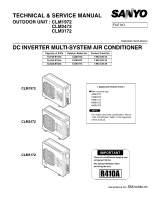
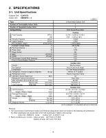
TECHNICAL & SERVICE MANUAL OUTDOOR UNIT : CLM1972 CLM2472 CLM3172 FILE NO. Destination: North America DC INVERTER MULTI-SYSTEM AIR CONDITIONER Capacity at 230V 19,700 BTU/h 25,400 BTU/h 30,600 BTU/h Outdoor Model No. CLM1972 CLM2472 CLM3172 Product Code No. 1 852 330 33 1 852 330 34 1 852 330 - Sanyo CLM2472 | Service Manual - Page 2
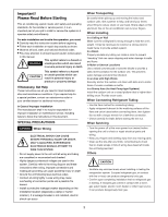
service person, it is an important part of your job to install or service the system so it operates safely and efficiently. For safe installation and trouble-free operation, you must: Carefully read this instruction wood or metal frame to provide added support. In a Room Properly insulate any tubing - Sanyo CLM2472 | Service Manual - Page 3
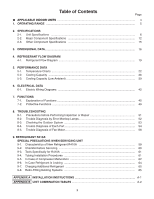
TROUBLESHOOTING 8-1. Precautions before Performing Inspection or Repair 51 8-2. Trouble Diagnosis by Error Monitop Lamps 52 8-3. Checking the Outdoor System 53 8-4. Trouble Diagnosis of Each Part 54 8-5. Trouble Diagnosis of Fan Motor 58 9. REFRIGERANT R410A: SPECIAL PRECAUTIONS WHEN SERVICING - Sanyo CLM2472 | Service Manual - Page 4
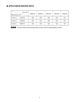
INDOOR UNITS Indoor Unit Multi-Outdoor Unit KMS0772 3-Room CLM1972 YES 4-Room CLM2472 YES 4-Room CLM3172 YES KMS0972 YES YES YES KMS1272 YES YES YES KMS1872 YES YES YES KMS2472 NO YES YES NOTE The table lists the wall-mounted type of indoor units as representative models. 4 - Sanyo CLM2472 | Service Manual - Page 5
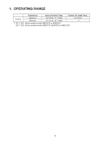
1. OPERATING RANGE Temperature Indoor Air Intake Temp. Outdoor Air Intake Temp. Cooling Maximum Minimum 95 °F D.B. / 71 °F W.B. 67 °F D.B. / 57 °F W.B. 115 °F D.B. *1 *1 32 °F D.B.: When combined with KMS1872 or KMS2472 23 °F D.B.: When combined with KMS0772, KMS0972 or KMS1272 5 - Sanyo CLM2472 | Service Manual - Page 6
BTU/Wh A A Features Control Fan Speeds Compressor Refrigerant / Amount charged at shipment Refrigerant Control Operation Sound (High) Cool combination unit, please refer to the "Unit Combination Tables" in this manual. Indoor Unit : KMS0972 3units Outdoor Unit : CLM1972 1unit 2. Rating - Sanyo CLM2472 | Service Manual - Page 7
BTU/Wh A A Features Control Fan Speeds Compressor Refrigerant / Amount charged at shipment Refrigerant Control Operation Sound (High) Cool combination unit, please refer to the "Unit Combination Tables" in this manual. Indoor Unit : KMS0972 3units Outdoor Unit : CLM1972 1unit 2. Rating - Sanyo CLM2472 | Service Manual - Page 8
BTU/Wh A A Features Control Fan Speeds Compressor Refrigerant / Amount charged at shipment Refrigerant Control Operation Sound (High) Cool refer to the "Unit Combination Tables" in this manual. Indoor Unit : KMS0972 3units Outdoor Unit : CLM2472 1unit 2. Rating conditions are: Cooling : Indoor - Sanyo CLM2472 | Service Manual - Page 9
BTU/Wh A A Features Control Fan Speeds Compressor Refrigerant / Amount charged at shipment Refrigerant Control Operation Sound (High) Cool refer to the "Unit Combination Tables" in this manual. Indoor Unit : KMS0972 3units Outdoor Unit : CLM2472 1unit 2. Rating conditions are: Cooling : Indoor - Sanyo CLM2472 | Service Manual - Page 10
BTU/Wh A A Features Control Fan Speeds Compressor Refrigerant / Amount charged at shipment Refrigerant Control Operation Sound (High) Cool combination unit, please refer to the "Unit Combination Tables" in this manual. Indoor Unit : KMS0972 4units Outdoor Unit : CLM3172 1unit 2. Rating - Sanyo CLM2472 | Service Manual - Page 11
BTU/Wh A A Features Control Fan Speeds Compressor Refrigerant / Amount charged at shipment Refrigerant Control Operation Sound (High) Cool combination unit, please refer to the "Unit Combination Tables" in this manual. Indoor Unit : KMS0972 4units Outdoor Unit : CLM3172 1unit 2. Rating - Sanyo CLM2472 | Service Manual - Page 12
2-2. Major Component Specifications 2-2-1. Outdoor Unit Outdoor Unit CLM1972 Control PCB Part No. Controls Control Circuit Fuse Compressor Type Compressor Model / Nominal Output Compressor Oil ... Amount Pints (cc) Coil Resistance (Ambient Temp. 68 °F (20 °C)) Ohm Safety Device CT (Peak - Sanyo CLM2472 | Service Manual - Page 13
Unit CLM2472 Control PCB Part No. Controls Control Circuit Fuse Compressor Type Compressor Model / Nominal Output Compressor Oil ... Amount Pints (cc) Coil Resistance (Ambient Temp. 68 °F (20 °C)) Ohm Safety Device CT (Peak current cut-off control) Compressor Discharge Temp. Control - Sanyo CLM2472 | Service Manual - Page 14
CLM3172 Control PCB Part No. Controls Control Circuit Fuse Compressor Type Compressor Model / Nominal Output Compressor Oil ... Amount Pints (cc) Coil Resistance (Ambient Temp. 68 °F (20 °C)) Ohm Safety Device CT (Peak current cut-off control) Compressor Discharge Temp. Control Operation - Sanyo CLM2472 | Service Manual - Page 15
41 50 59 68 (-20)(-15)(-10) (-5) (0) (5) (10) (15) (20) Temperature F ( C) Sensor Name Compressor temp sensor Model No. of sensor TKS293B CLM1972 1 Quantity of Sensor CLM2472 1 Resistance (k ohm) 200 180 160 140 120 100 80 60 40 20 0 32 50 68 86 104 122 140 158 176 194 (0) (10) (20 - Sanyo CLM2472 | Service Manual - Page 16
1-3/8 ID:23/32 2-ID:15/16 12-19/32(320) 13-19/32 14-17/32 35-7/16(900) 2-15/16 Wide tube service valve dia.3/8" (9.52) × 3 Narrow tube service valve dia.1/4" (6.35) × 3 29-1/8(740) 4-7/16 2-15/16 2-3/4 5-29/32 2-27/32 2-3/4 23/32 1-13/16 2-1/16 2-1/32 4-1/2 Unit: inch(mm) 16 - Sanyo CLM2472 | Service Manual - Page 17
Outdoor Unit CLM2472 11-17/32 23-15/16 5-11/32 15/32 1-3/8 ID:23/32 2-ID:15/16 12-19/32(320) 13-19/32 14-17/32 35-7/16(900) 2-15/16 Wide tube service valve dia.3/8" (9.52) × 3 Narrow tube service valve dia.1/4" (6.35) × 4 Wide tube service valve dia.1/2" (12.70) × 1 4-7/16 2-15 - Sanyo CLM2472 | Service Manual - Page 18
ID:15/16 12-19/32(320) 13-19/32 14-17/32 35-7/16(900) 2-15/16 Wide tube service valve dia.3/8" (9.52) × 2 Narrow tube service valve dia.1/4" (6.35) × 4 Wide tube service valve dia.1/2" (12.70) × 2 35-1/32(890) 4-7/16 2-15/16 2-3/4 2-3/4 5-29/32 2-7/8 2-3/4 2-3/4 23/32 1-13/16 2-1/16 2-13/32 - Sanyo CLM2472 | Service Manual - Page 19
BW AW Header Outdoor unit Sub Main accumulator accumulator High pressure switch H.P. Compressor Heat exchanger Narrow tube O.D.1/4" O.D.1/4" O.D.1/4" Service valve on narrow tube CN Electric expansion valve M BN M AN M Strainer Header Cooling cycle Insulation of Refrigerant Tubing - Sanyo CLM2472 | Service Manual - Page 20
Outdoor Unit CLM2472 Indoor unit Wide tube O.D.3/8" O.D.3/8" O.D.3/8" O.D.1/2" Service valve on wide tube DW CW BW AW Header Outdoor unit Sub Main accumulator accumulator High pressure switch H.P. Narrow tube O.D.1/4" O.D.1/4" O.D.1/4" O.D.1/4" Service valve on narrow tube DN Electric - Sanyo CLM2472 | Service Manual - Page 21
on wide tube DW CW BW AW Header Outdoor unit Sub Main accumulator accumulator High pressure switch H.P. Narrow tube O.D.1/4" O.D.1/4" O.D.1/4" O.D.1/4" Service valve on narrow tube DN Electric expansion valve M CN M BN M AN M Strainer Header Heat exchanger Compressor Cooling cycle - Sanyo CLM2472 | Service Manual - Page 22
Lo fan 174 (1.2) 160 (1.1) Hi fan HH fan Indoor air temp. 86°F 80°F 75°F (30°C) (27°C) (24°C) Low pressure at wide tube service valve psig (MPaG) 146 (1.0)77 86 95 104 (25) (30) (35) (40) Outdoor air temperature °F (°C) (2) Operating current performance chart Lo fan 5 Hi - Sanyo CLM2472 | Service Manual - Page 23
Low pressure at wide tube service valve psig (MPaG) Outdoor Unit CLM1972 Indoor Unit KMS0972 × 1 Cooling Characteristics (RH : 46%, Indoor fan speed : High fan) (230V, 60Hz) (1) Low pressure performance chart 188 (1.3) - Sanyo CLM2472 | Service Manual - Page 24
Low pressure at wide tube service valve psig (MPaG) Outdoor Unit CLM1972 Indoor Unit KMS1272 × 1 Cooling Characteristics (RH : 46%, Indoor fan speed : High fan) (230V, 60Hz) (1) Low pressure performance chart 174 (1.2) - Sanyo CLM2472 | Service Manual - Page 25
Low pressure at wide tube service valve psig (MPaG) Outdoor Unit CLM1972 Indoor Unit KMS1872 × 1 Cooling Characteristics (RH : 46%, Indoor fan speed : High fan) (230V, 60Hz) (1) Low pressure performance chart 174 (1.2) - Sanyo CLM2472 | Service Manual - Page 26
Low pressure at wide tube service valve psig (MPaG) 5-1-2. Temperature Charts (CLM2472) Outdoor Unit CLM2472 Indoor Unit KMS0772 × 1 Cooling Characteristics (RH : 46%, Indoor fan speed : High fan) (230V, 60Hz) (1) Low pressure performance chart 188 (1.3) Lo fan 174 (1.2) 160 (1.1) Hi fan - Sanyo CLM2472 | Service Manual - Page 27
Low pressure at wide tube service valve psig (MPaG) Outdoor Unit CLM2472 Indoor Unit KMS0972 × 1 Cooling Characteristics (RH : 46%, Indoor fan speed : High fan) (230V, 60Hz) (1) Low pressure performance chart 188 (1.3) Lo fan Hi fan HH fan - Sanyo CLM2472 | Service Manual - Page 28
Low pressure at wide tube service valve psig (MPaG) Outdoor Unit CLM2472 Indoor Unit KMS1272 × 1 Cooling Characteristics (RH : 46%, Indoor fan speed : High fan) (230V, 60Hz) (1) Low pressure performance chart 174 (1.2) Lo fan 160 (1.1) Hi fan HH - Sanyo CLM2472 | Service Manual - Page 29
Low pressure at wide tube service valve psig (MPaG) Outdoor Unit CLM2472 Indoor Unit KMS1872 × 1 Cooling Characteristics (RH : 46%, Indoor fan speed : High fan) (230V, 60Hz) (1) Low pressure performance chart 174 (1.2) Lo fan 160 (1.1) HH fan Hi - Sanyo CLM2472 | Service Manual - Page 30
Low pressure at wide tube service valve psig (MPaG) Outdoor Unit CLM2472 Indoor Unit KMS2472 × 1 Cooling Characteristics (RH : 46%, Indoor fan speed : High fan) (230V, 60Hz) (1) Low pressure performance chart 174 (1.2) Lo fan 160 (1.1) 146 (1.0) Hi fan - Sanyo CLM2472 | Service Manual - Page 31
Indoor fan speed : High fan) (230V, 60Hz) (1) Low pressure performance chart 174 (1.2) Lo fan Hi fan Hi fan HH fan Low pressure at wide tube service valve psig (MPaG) 146 (1.0) 118 (0.8) Indoor air temp. 86°F (30°C) 80°F (27°C) 75°F (24°C) 90 (0.6)77 86 95 104 (25) (30) (35) (40 - Sanyo CLM2472 | Service Manual - Page 32
Low pressure at wide tube service valve psig (MPaG) Outdoor Unit CLM3172 Indoor Unit KMS0972 × 1 Cooling Characteristics (RH : 46%, Indoor fan speed : High fan) (230V, 60Hz) (1) Low pressure performance chart 174 (1.2) - Sanyo CLM2472 | Service Manual - Page 33
fan speed : High fan) (230V, 60Hz) (1) Low pressure performance chart 174 (1.2) Lo fan Hi fan Hi fan HH fan Low pressure at wide tube service valve psig (MPaG) 146 (1.0) 118 (0.8) Indoor air temp. 86°F (30°C) 80°F (27°C) 75°F (24°C) 90 (0.6)77 86 95 104 (25) (30) (35) (40) Outdoor - Sanyo CLM2472 | Service Manual - Page 34
(RH : 46%, Indoor fan speed : High fan) (230V, 60Hz) (1) Low pressure performance chart 174 (1.2) Lo fan Hi fan Low pressure at wide tube service valve psig (MPaG) 146 (1.0) 118 (0.8) Indoor air temp. 86°F 80°F (30°C) (27°C) 75°F (24°C) 90 (0.6)77 86 95 104 (25) (30) (35) (40 - Sanyo CLM2472 | Service Manual - Page 35
(RH : 46%, Indoor fan speed : High fan) (230V, 60Hz) (1) Low pressure performance chart 174 (1.2) Lo fan Hi fan 146 (1.0) Low pressure at wide tube service valve psig (MPaG) 118 (0.8) 90 (0.6)77 (25) Indoor air temp. 86°F (30°C) 80°F (27°C) 75°F (24°C) 86 95 104 (30) (35) (40) Outdoor - Sanyo CLM2472 | Service Manual - Page 36
5-2. Cooling Capacity Outdoor Unit : CLM1972 Indoor Unit : KMS0972 × 3 Power Supply : 230V Single Phase 60Hz < Cooling Capacity > RATING CAPACITY: INDOOR ENT. TEMP. oF (oC) W.B. D.B. 19,700 BTU/h 65 (18.3) TC 19,800 AIR FLOW RATE: OUTDOOR AMBIENT TEMP. oF (oC) 75 (23.9) 85 (29.4) 95 (35 - Sanyo CLM2472 | Service Manual - Page 37
Outdoor Unit : CLM2472 Indoor Unit : KMS0972 × 3 Power Supply : 230V Single Phase 60Hz < Cooling Capacity > RATING CAPACITY: INDOOR ENT. TEMP. oF (oC) W.B. D.B. 25,400 BTU/h 65 (18.3) TC 25, - Sanyo CLM2472 | Service Manual - Page 38
Outdoor Unit : CLM3172 Indoor Unit : KMS0972 × 4 Power Supply : 230V Single Phase 60Hz < Cooling Capacity > RATING CAPACITY: INDOOR ENT. TEMP. oF (oC) W.B. D.B. 30,600 BTU/h 65 (18.3) TC 31,170 AIR FLOW RATE: OUTDOOR AMBIENT TEMP. oF (oC) 75 (23.9) 85 (29.4) 95 (35.0) 30,000 28,730 28, - Sanyo CLM2472 | Service Manual - Page 39
5-3. Cooling Capacity (Low Ambient) Outdoor Unit : CLM1972 Indoor Unit : KMS0972 × 3 Power Supply : 230V Single Phase 60Hz < Cooling Capacity (Low Ambient) > RATING CAPACITY: INDOOR ENT. TEMP. oF (oC) W.B. D.B. 19,700 BTU/h TC AIR FLOW RATE: OUTDOOR AMBIENT TEMP. oF (oC) 20 (-6.7) 25 - Sanyo CLM2472 | Service Manual - Page 40
Outdoor Unit : CLM2472 Indoor Unit : KMS0972 × 3 Power Supply : 230V Single Phase 60Hz < Cooling Capacity (Low Ambient) > RATING CAPACITY: INDOOR ENT. TEMP. oF (oC) W.B. D.B. 25,400 BTU/h TC AIR - Sanyo CLM2472 | Service Manual - Page 41
Outdoor Unit : CLM3172 Indoor Unit : KMS0972 × 4 Power Supply : 230V Single Phase 60Hz < Cooling Capacity (Low Ambient) > RATING CAPACITY: INDOOR ENT. TEMP. oF (oC) W.B. D.B. 30,600 BTU/h TC AIR FLOW RATE: OUTDOOR AMBIENT TEMP. oF (oC) 20 (-6.7) 25 (-3.9) 35 (1.7) 30,720 30,740 30,820 - Sanyo CLM2472 | Service Manual - Page 42
sure to WARNING disconnect power before checking, servicing and/or cleaning any electrical parts. 8FA2-5257-59400-1 42 COMPRESSOR THERMISTOR BLK OLR) RED BLU BRN WHT ORG 12345678 123456 12345678 123456 CN03 CN02 EXPANSION BOARD C-TH 1234 1234 1234 1234 CN01 MV2 12345 12345 W SICOM2 SI-C - Sanyo CLM2472 | Service Manual - Page 43
THERMISTOR YEL YEL YEL YEL BN THERMISTOR 1234 1234 B-TH CONTROLLER WHT WHT 11 (1P)CONNECTOR 11 (1P) WHT CONNECTOR 12345678 123456 12345678 123456 CN03 CN02 EXPANSION BOARD D-TH C-TH MV3 1234 1234 12345 1234 servicing and/or cleaning any electrical parts. Outdoor Unit CLM2472 - Sanyo CLM2472 | Service Manual - Page 44
THERMISTOR YEL YEL YEL YEL BN THERMISTOR 1234 1234 B-TH CONTROLLER WHT WHT 11 (1P)CONNECTOR 11 (1P) WHT CONNECTOR 12345678 123456 12345678 123456 CN03 CN02 EXPANSION BOARD D-TH C-TH MV3 1234 1234 12345 1234 servicing and/or cleaning any electrical parts. Outdoor Unit CLM3172 - Sanyo CLM2472 | Service Manual - Page 45
stopped. Positioning of the outdoor unit electric expansion valve is performed. If automatic operation mode has been selected with the remote controller, operation begins in SENSOR DRY, or COOL mode depending on the room temperature and outdoor temperature at the time operation starts. This - Sanyo CLM2472 | Service Manual - Page 46
, it is assumed that there has been no significant change in the indoor and outdoor temperatures, and the previous conditions (COOL) are stored. Frequency control (Hz) (25) Hz (35) Hz (45) Hz (55) Hz (senconds) Outdoor air temperature is below 32 °F. Outdoor air temperature is 32 °F or higher - Sanyo CLM2472 | Service Manual - Page 47
/conditions SENSOR The ON/OFF operation DRY button on the remote controller is pressed. Unit operation Explanation The operation lamp illuminates. The indoor fan operates at the set fan speed. The outdoor unit stops. The outdoor unit - Sanyo CLM2472 | Service Manual - Page 48
< Low Ambient Cooling Operation > NOTE The following descriptions of low ambient cooling operation are applied only to CLM1972 and CLM2472 When the outdoor air temperature reaches 57.2 °F (14 °C ) or less during the cooling operation, the operation mode is switched to low ambient cooling operation. - Sanyo CLM2472 | Service Manual - Page 49
later, if Point C is exceeded. (May operate when sudden voltage fluctuations occur. Indicates trouble.) (1) Automatic frequency control The operating frequency is reduced automatically, or operation is stopped, in order to control the operating current so that it is at or below the values shown in - Sanyo CLM2472 | Service Manual - Page 50
temperature. (°F) Compressor discharge temperature Trip (230) (223) (212) (194) 5Hz every 30 sec. reduction 2Hz every 30 sec. reduction No control Increase prohibit range (Hz reduction) * Within the increase-prohibit range, the range changes to the Hz reduction range (2 Hz every 30 seconds - Sanyo CLM2472 | Service Manual - Page 51
to touch any electrified parts before the control circuit board Power Lamp (red) turns OFF. If the outdoor control circuit board is normal, approximately 180 thought there might be trouble with the outdoor control circuit board. For example, if the outdoor control circuit board fuse has blown, - Sanyo CLM2472 | Service Manual - Page 52
device has activated or there is a sensor failure in the outdoor unit, the 4 error monitor lamps on the outdoor control circuit board will indicate the nature of the trouble. : ON : OFF Error Monitor Lamp ERR0 ERR1 ERR2 ERR3 Error Contents Sensor for compressor discharge temp Sensor for heat - Sanyo CLM2472 | Service Manual - Page 53
plate. 2 • Short-circuit the T-RUN terminal to the COM terminal of TEST/T-RUN terminals. Check items (unit operation) • The LED (red) on the control board must illuminate. • The compressor and fan motor must turn ON. (They turn ON about (70) seconds later after the power is turned ON.) NOTE If - Sanyo CLM2472 | Service Manual - Page 54
8-4. Trouble Diagnosis of Each Part 8-4-1. Problems of Each Part and Inspection Points For details about the inspection points, refer to the Inspection Points for Each Part. Problems Indoor unit Inspection points Outdoor unit Others No. of Inspection Points for Each part Indoor unit Indoor - Sanyo CLM2472 | Service Manual - Page 55
cool or cooling performance is inadequate. Problems Indoor unit Inspection points Breaker Refrigerant gas pressure Outdoor unit Others No. of Inspection Points for Each part (8) (9) 8-4-2. Inspection Points for Each Part (1) Outdoor control circuit board Refer to 8-3-1. Checking the outdoor - Sanyo CLM2472 | Service Manual - Page 56
identify them. Controller check No voltage on circuit board Voltage varies Use CLM2472 CLM3172 MV0 MV1 MV2 MV3 Check the illumination of the red Power Lamp. Replace the controller part is normal. Check elsewhere. Use the special service *1 If you have manually checked the electric expansion - Sanyo CLM2472 | Service Manual - Page 57
when the circuit is charged 2 to 3 times with refrigerant gas (0.44 lbs each time), or if the change is small, then the problem may not be refrigerant shortage. The problem may be a blockage of the refrigerant circuit. 1. Check that there is no internal leakage inside the 4-way valve: At the low - Sanyo CLM2472 | Service Manual - Page 58
DC fan motor contains an internal control PCB. Therefore, it is not possible to measure the coil resistance, and the following procedure should be used to check the motor. Perform the trouble diagnosis by Test Run mode described on Installation Instructions of indoor unit. Important: (A) Turn OFF - Sanyo CLM2472 | Service Manual - Page 59
9. REFRIGERANT R410A: SPECIAL PRECAUTIONS WHEN SERVICING UNIT 9-1. Characteristics of New Refrigerant R410A 9-1-1. What is New Refrigerant R410A? R410A is a new refrigerant that contains two types of pseudo-non-azeotropic refrigerant mixture. - Sanyo CLM2472 | Service Manual - Page 60
9-2. Checklist before Servicing Use a clutch-type flare tool for R410A or the conventional flare tool. Note that sizes of the resultant flares differ between these two tools. Where a - Sanyo CLM2472 | Service Manual - Page 61
mistakenly charged to this unit, shape and external diameter of the service port screw has been altered. R410A : 5/16" R22, R407C : 1/4" 9-4. on tubing installation procedures, refer to the installation manuals attached to the indoor unit and outdoor unit. 61 - Sanyo CLM2472 | Service Manual - Page 62
9-5. In Case of Compressor Malfunction CAUTION Should the compressor malfunction, be sure to make the switch to a replacement compressor as quickly as possible. Use only the tools indicated exclusively for R410A. See "9-3. Tools Specifically for R410A." 9-5-1. Procedure for Replacing Compressor - Sanyo CLM2472 | Service Manual - Page 63
in liquid state using the service port of the wide tube service valve. The proper amount is listed on the unit's nameplate. When 0.20 = 2.76 Kg) For the remaining refrigerant, refer to the instructions of the refrigerant manufacturer. If using a charging cylinder, transfer the specified - Sanyo CLM2472 | Service Manual - Page 64
9-6. In Case Refrigerant is Leaking CAUTION Never attempt to charge additional refrigerant when refrigerant has been leaking from the unit. Follow the procedure described below to locate points of leaks and carry out repairs, then recharge the refrigerant. (1) Detecting Leaks Use the detector for - Sanyo CLM2472 | Service Manual - Page 65
of refrigerant as stated in this service manual or the installation manual that came with the indoor unit. Charge additional refrigerant in liquid state only. CAUTION Never charge additional refrigerant if refrigerant is leaking from the unit. Follow instructions given in "9-6. In Case Refrigerant - Sanyo CLM2472 | Service Manual - Page 66
APPENDIX A INSTALLATION INSTRUCTIONS CLM1972 CLM2472 CLM3172 (II-852-6-4190-214-00-3) A-1 - Sanyo CLM2472 | Service Manual - Page 67
Unit CM1972 CM2472 CM3172 CLM1972 CLM2472 CLM3172 Combine indoor and outdoor units only as listed in the combination tables for 3-room or 4-room outdoor unit as shown in its respective manual. Power Source: 60 Hz, single-phase, 230 / 208 VAC Be sure to read the yellow instruction sheet attached - Sanyo CLM2472 | Service Manual - Page 68
service person, it is an important part of your job to install or service the system so it operates safely and efficiently. For safe installation and trouble-free operation, you must: G Carefully read this instruction wood or metal frame to provide added support. ...In a Room Properly insulate any - Sanyo CLM2472 | Service Manual - Page 69
the air conditioning system. Please read over the entire set of instructions for the indoor and outdoor units and make sure all accessory parts listed are with the system before beginning. If the electric wiring diagram does not appear in this manual, please check for the diagram on the indoor unit - Sanyo CLM2472 | Service Manual - Page 70
1-5. Additional Materials Required for Installation 1. Refrigeration (armored) tape 2. Insulated staples or clamps for connecting wire (See local codes) 3. Putty 4. Refrigeration lubricant 5. Clamps or saddles to secure refrigerant tubing Indoor unit 2. Installation Site Selection 2-1. Indoor - Sanyo CLM2472 | Service Manual - Page 71
Amount of Additional Refrigerant (oz./ft.)* CM1972/CLM1972 82 150 (L1+L2+L3) 150 (L1+L2+L3) 50 - CM2472/CLM2472 82 150 (L1+L2+L3+L4) 200 (L1+L2+L3+L4) 50 0.22 CM3172/CLM3172 100 150 (L1+L2+ necessary. For more detailed charging information, refer to the Technical & Service Manual. 5 - Sanyo CLM2472 | Service Manual - Page 72
unit (KMS0772,KMS0972,KMS1272) (KMS0772,KMS0972,KMS1272) (KMS1872) Fig. 4b (2) Connecting indoor unit for CM2472/CLM2472 (A) Outdoor unit D 3/8"(9.52mm) 3/8"(9.52mm) C 1/4"(6.35mm) 3/8"(9.52mm) 3/8"(9.52mm) B 1/4"(6.35mm) 3/8"(9.52mm) 3/8"(9.52mm) A 1/4"(6.35mm) 3/8"(9.52mm) 1/2"(12 - Sanyo CLM2472 | Service Manual - Page 73
(B) Outdoor unit D 3/8"(9.52mm) C 3/8"(9.52mm) B 3/8"(9.52mm) A 1/2"(12.70mm) 1/4"(6.35mm) 1/4"(6.35mm) 1/4"(6.35mm) 1/4"(6.35mm) 3/8"(9.52mm) Indoor unit (KMS0772,KMS0972,KMS1272) 3/8"(9.52mm) (KMS0772,KMS0972,KMS1272) 3/8"(9.52mm) (KMS0772,KMS0972,KMS1272) 1/2"(12.70mm) (KMS1872) Fig. - Sanyo CLM2472 | Service Manual - Page 74
(3) Connecting indoor unit for CM3172/CLM3172 (A) Outdoor unit D 3/8"(9.52mm) C 3/8"(9.52mm) B 1/2"(12.70mm) A 1/2"(12.70mm) 3/8"(9.52mm) 1/4"(6.35mm) 3/8"(9.52mm) 1/4"(6.35mm) 3/8"(9.52mm) 1/4"(6.35mm) 3/8"(9.52mm) 1/4"(6.35mm) Indoor unit (KMS0772,KMS0972,KMS1272) (KMS0772,KMS0972,KMS1272) ( - Sanyo CLM2472 | Service Manual - Page 75
(D) Outdoor unit D 3/8"(9.52mm) C 3/8"(9.52mm) B 1/2"(12.70mm) A 1/2"(12.70mm) Indoor unit 3/8"(9.52mm) (KMS0772,KMS0972,KMS1272) 1/4"(6.35mm) 3/8"(9.52mm) (KMS0772,KMS0972,KMS1272) 1/4"(6.35mm) 3/8"(9.52mm) (KMS0772,KMS0972,KMS1272) 1/4"(6.35mm) 5/8"(15.88mm) (KMS2472) 1/4"(6.35mm) - Sanyo CLM2472 | Service Manual - Page 76
level to reduce humidity and protect the unit against possible water damage and decreased service life. (Figs. 5c and 5d) CAUTION A solid base must not cover the NOTE It is recommended to use baffle plates for models CLM1972, CLM2472 and CLM3172. The baffle plates are not normally required for the - Sanyo CLM2472 | Service Manual - Page 77
) AE G F B G Fig. 5g D Fig. 5h For Air Intake Dimensions A B C D E F G Model CLM1972, CLM2472 (inch) 25-3/16 25/32 1-31/32 25 10-5/8 10-5/8 25/64 (mm) 640 20 50 635 270 : 0.0394 to 0.0472" (1.0 to 1.2 mm) (2) Parts required (field supply except for screws) Air Intake Baffle Item - Sanyo CLM2472 | Service Manual - Page 78
side R Panel front Panel side L Panel side L Fig. 5i Fig. 5j NOTE G In order to prevent contact of the bolts and heat exchanger and other parts inside the unit, install the windbaffle using bolts from inside the unit and fasten the bolts with nuts from outside the unit. G When the windbaffle - Sanyo CLM2472 | Service Manual - Page 79
16 5-11/32 15/32 A A 35-7/16 (900) 2-29/32 Service valve on narrow tube side (Outer diameter 1/4"(6.35)) Service valve on wide tube side (Outer diameter 3/8"(9.52)) 2-3/4 29-1/8 (740) 2-3/4 2-15/16 2-27/32 23/32 4-7/16 5-29/32 (2) CM2472/CLM2472 23-15/16 5-11/32 15/32 A 12-19/32 13 - Sanyo CLM2472 | Service Manual - Page 80
sure to connect indoor and outdoor units only in combinations that are listed in the catalog or in the combination table that was provided Fasten with anchor bolts (not provided) (3/8" or M10, 4 locations) Fig. 7 Service space Indoor unit D Indoor unit C Indoor unit B Indoor unit A Over 10"(25cm - Sanyo CLM2472 | Service Manual - Page 81
3. Installation Process 3-1. Embedding the Tubing and Wiring G Do not connect tubes to locations that are embedded. G Be sure to bind refrigerant tubing and inter-unit cables together with vinyl tape. G The power cable must be obtained on-site. (#12: Less than 85 ft.) # ... AWG (American Wire Gauge) - Sanyo CLM2472 | Service Manual - Page 82
. 430 - 540 lbs·in (490 - 610 kgf·cm) Approx. 590 - 710 lbs·in (680 - 820 kgf·cm) Union Flare nut Fig. 13 Service valve on D narrow tube side C B A Service valve on wide tube side Fig. 14 16 Apply the provided labels to the indoor and outdoor unit tubing connectors to prevent errors - Sanyo CLM2472 | Service Manual - Page 83
to match refrigerant tubing and electric wiring between indoor and outdoor units. For more details, refer to "Tubing Check Control" in the Technical & Service Manual. 3-6. Insulation of Refrigerant Tubing I M P O R TA N T To prevent heat loss and wet floors due to dripping of condensation, both - Sanyo CLM2472 | Service Manual - Page 84
may lead to corrosion of parts in the refrigerant system Service valve on narrow Service valve on wide tube side adapter, read the vacuum pump adapter manual, and use the External diameter of service port R410A: 5/16" Fig. 21 problem. G Use a hex wrench of a type to which force can be easily - Sanyo CLM2472 | Service Manual - Page 85
. If it does return, find and repair the leak, then apply the vacuum again.) (6) With a hex wrench, turn the valve stem on the narrow tube service valve counter-clockwise by 90 degrees (1/4 turn) for 10 seconds, and then turn the stem clockwise to close it again. CAUTION Be sure to completely - Sanyo CLM2472 | Service Manual - Page 86
is running, apply liquid soap to check for any gas leaks around the service valves or caps. (14) If there is no leakage, stop the air to protect the indoor unit heat exchanger from freezing and does not indicate a problem. (4) Disconnect the manifold gauge and the inter-unit tubes, and attach the - Sanyo CLM2472 | Service Manual - Page 87
Instructions to touch the refrigerant tubing, compressor, or any moving parts of the fan. (6) Unauthorized changes in the internal wiring NFPA70. Table 6 Model AWG CM1972 / CLM1972 CM2472 / CLM2472 CM3172 / CLM3172 Max. Power Line Length (ft.) Max. Control Line Length (ft.) (A) (B) (C) (#12) - Sanyo CLM2472 | Service Manual - Page 88
No wire should be allowed to touch refrigerant tubing, the compressor, or any moving part. G Be sure to connect power wires correctly match- ing up numbers on terminals 3 indoor units with CM1972/CLM1972 4 indoor units with CM2472/CLM2472, CM3172/CLM3172 L1 Power supply L2 Single-phase 230/208VAC - Sanyo CLM2472 | Service Manual - Page 89
hazard may also exist. Therefore, be sure all wiring is tightly connected. When connecting each power wire to the corresponding terminal, follow the instructions "How to connect wiring to the terminal" and fasten the wire securely tight with the fixing screw of the terminal plate. How to connect - Sanyo CLM2472 | Service Manual - Page 90
5-5. Wiring Instructions for the Outdoor Unit CAUTION G Be sure to correctly align inter-unit cables A, B, C and D. Outdoor unit A Terminal board 1 2 Indoor unit A 1 2 3 4 5 6 7 8 9 10 11 12 A is the indoor unit with refrigerant tubing that is connected to service valve A (top) of the outdoor - Sanyo CLM2472 | Service Manual - Page 91
the unit according to your local codes. 6. Test Run Performing a test run G Refer to the test run procedures in the indoor unit installation manual. G Perform the test run separately for each connected indoor unit. If 2 units are operated simultaneously, it is not possible to correctly check for - Sanyo CLM2472 | Service Manual - Page 92
The strength of the installation location is sufficient to support the A/C weight. The indoor and outdoor units unit cables are securely fastened to the terminal board. Inter-unit cables are securely fixed. The service valves are fully open. Remote controller signals are being positively received. 26 - Sanyo CLM2472 | Service Manual - Page 93
APPENDIX B UNIT COMBINATION TABLES < List of Combination Tables > Name of Combination Table Model No. of Outdoor Unit 3-Room Outdoor Unit Combination Table CLM1972 4-Room Outdoor Unit Combination Table CLM2472 4-Room Outdoor Unit Combination Table CLM3172 Remarks OI-852-6-4180-827-00-2 OI- - Sanyo CLM2472 | Service Manual - Page 94
of Connectable Indoor Units> The combinations of the indoor units listed in Table 1 and Table 2 are combinations solely of 3-room operation column of Table 1, operating all these units concurrently may result in trouble. At a time like this, shut down at least one of the 3 85264180827002 © SANYO 2008 - Sanyo CLM2472 | Service Manual - Page 95
19700 ( 9800 - 19700 ) 9000 + 11900 + 11900 = 32800 5410 7145 7145 19700 ( 9800 - 19700 ) 11900 + 11900 + 11900 = 35700 6567 6567 6567 19700 ( 9800 - 19700 ) The table lists the wall-mounted type of indoor units as representative models. -2- - Sanyo CLM2472 | Service Manual - Page 96
19700 ( 9800 - 19700 ) 9000 + 11900 + 11900 = 32800 5410 7145 7145 19700 ( 9800 - 19700 ) 11900 + 11900 + 11900 = 35700 6567 6567 6567 19700 ( 9800 - 19700 ) The table lists the wall-mounted type of indoor units as representative models. -3- - Sanyo CLM2472 | Service Manual - Page 97
Outdoor Unit Combination Table CLM2472 The combinations of the indoor units listed in Table 1 and operation column of Table 1, operating all these units concurrently may result in trouble. At a time like this, shut down at least one of the © SANYO 2008 - Sanyo CLM2472 | Service Manual - Page 98
< Combinations of operatable indoor units > Voltage Rating : 230V 60Hz CLM2472 (Rated cooling capacity at 230V: 25400 BTU/h) NOTE 7500 : KMS0772 9000 : KMS0972 three indoor units may be operated concurrently. The table lists the wall-mounted type of indoor units as representative models. -2- - Sanyo CLM2472 | Service Manual - Page 99
Voltage Rating : 208V 60Hz CLM2472 (Rated cooling capacity at 208V: 24400 BTU/h) NOTE 7500 : KMS0772 9000 : KMS0972 11900 : KMS1272 17500 : not run properly. Up to three indoor units may be operated concurrently. The table lists the wall-mounted type of indoor units as representative models. -3- - Sanyo CLM2472 | Service Manual - Page 100
of Connectable Indoor Units> The combinations of the indoor units listed in Table 1 and Table 2 are combinations solely of 4-room operation column of Table 1, operating all these units concurrently may result in trouble. At a time like this, shut down at least one of the 4 85264180829002 © SANYO 2008 - Sanyo CLM2472 | Service Manual - Page 101
( 9800 - 30600 ) 30600 ( 9800 - 30600 ) 30600 ( 9800 - 30600 ) 30600 ( 9800 - 30600 ) 30600 ( 9800 - 30600 ) 30600 ( 9800 - 30600 ) 30600 ( 9800 - 30600 ) 30600 ( 9800 - 30600 ) The table lists the wall-mounted type of indoor units as representative models. -2- - Sanyo CLM2472 | Service Manual - Page 102
( 9800 - 28600 ) 28600 ( 9800 - 28600 ) 28600 ( 9800 - 28600 ) 28600 ( 9800 - 28600 ) 28600 ( 9800 - 28600 ) 28600 ( 9800 - 28600 ) 28600 ( 9800 - 28600 ) 28600 ( 9800 - 28600 ) The table lists the wall-mounted type of indoor units as representative models. -3- - Sanyo CLM2472 | Service Manual - Page 103
SANYO Commercial Solutions A Division of SANYO North America Corporation 1300 Michael Drive, Suite A Wood Dale, IL 60191, U.S.A. Sanyo Canada Inc. 1-300 Applewood Crescent, Concord, Ontario L4K 5C7, CANADA Oct. / 2008 (T)
-
 1
1 -
 2
2 -
 3
3 -
 4
4 -
 5
5 -
 6
6 -
 7
7 -
8
-
9
-
10
-
11
-
12
-
13
-
14
-
15
-
16
-
17
-
18
-
19
-
20
-
21
-
22
-
23
-
24
-
25
-
26
-
27
-
28
-
29
-
30
-
31
-
32
-
33
-
34
-
35
-
36
-
37
-
38
-
39
-
40
-
41
-
42
-
43
-
44
-
45
-
46
-
47
-
48
-
49
-
50
-
51
-
52
-
53
-
54
-
55
-
56
-
57
-
58
-
59
-
60
-
61
-
62
-
63
-
64
-
65
-
66
-
67
-
68
-
69
-
70
-
71
-
72
-
73
-
74
-
75
-
76
-
77
-
78
-
79
-
80
-
81
-
82
-
83
-
84
-
85
-
86
-
87
-
88
-
89
-
90
-
91
-
92
-
93
-
94
-
95
-
96
-
97
-
98
-
99
-
100
-
101
-
102
-
103
 |
 |
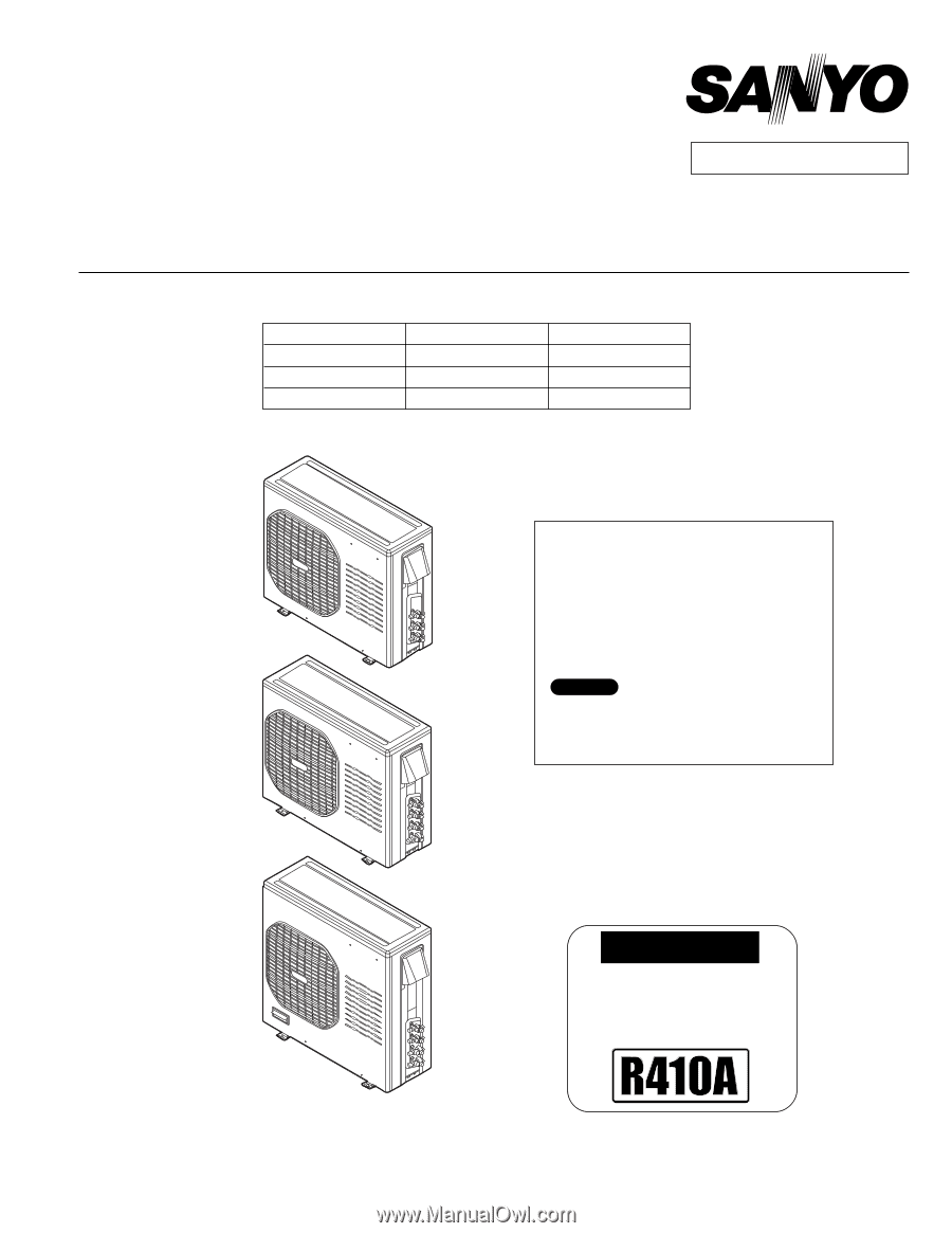
IMPORTANT
These air conditioners employ new
refrigerant R410A.
Pay special attention when
servicing the unit.
●
Wall mounted type
KMS0772
KMS0972
KMS1272
KMS1872
KMS2472
< Applicable Indoor Units >
TECHNICAL & SERVICE MANUAL
OUTDOOR UNIT : CLM1972
CLM2472
CLM3172
DC INVERTER MULTI-SYSTEM AIR CONDITIONER
Destination: North America
Product Code No.
1 852 330 33
1 852 330 34
1 852 330 35
REFERENCE NO.
SM
700680-03
Capacity at 230V
19,700 BTU/h
25,400 BTU/h
30,600 BTU/h
Outdoor Model No.
CLM1972
CLM2472
CLM3172
NOTE
CLM1972
CLM2472
CLM3172
For details about the combination, refer to
"Unit Combination Table" in the Appendix
of this manual.
FILE NO.