Sanyo CM1972 Service Manual
Sanyo CM1972 - 19,700 BTU Ductless Multi-Split Air Conditioner Manual
 |
View all Sanyo CM1972 manuals
Add to My Manuals
Save this manual to your list of manuals |
Sanyo CM1972 manual content summary:
- Sanyo CM1972 | Service Manual - Page 1
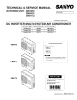
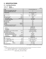
TECHNICAL & SERVICE MANUAL OUTDOOR UNIT : CM1972 CM2472 CM3172 FILE NO. Destination: North America DC INVERTER MULTI-SYSTEM AIR CONDITIONER Capacity at 230V 19,700 BTU/h 25,400 BTU/h 30,600 BTU/h Outdoor Model No. CM1972 CM2472 CM3172 Product Code No. 1 852 330 27 1 852 330 28 1 852 330 29 - Sanyo CM1972 | Service Manual - Page 2
and abnormal vibration. In an Area with High Winds Securely anchor the outdoor unit down with bolts and a metal frame. Provide a suitable air baffle. In a Snowy Area (for Heat Pump-type Systems) Install the outdoor unit on a raised platform that is higher than drifting snow. Provide snow vents - Sanyo CM1972 | Service Manual - Page 3
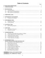
TROUBLESHOOTING 8-1. Precautions before Performing Inspection or Repair 47 8-2. Trouble Diagnosis by Error Monitop Lamps 48 8-3. Checking the Outdoor System 49 8-4. Trouble Diagnosis of Each Part 50 8-5. Trouble Diagnosis of Fan Motor 54 9. REFRIGERANT R410A: SPECIAL PRECAUTIONS WHEN SERVICING - Sanyo CM1972 | Service Manual - Page 4
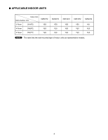
APPLICABLE INDOOR UNITS Indoor Unit Multi-Outdoor Unit KMS0772 3-Room CM1972 YES 4-Room CM2472 YES 4-Room CM3172 YES KMS0972 YES YES YES KMS1272 YES YES YES KMS1872 YES YES YES KMS2472 NO YES YES NOTE The table lists the wall-mounted type of indoor units as representative models. 4 - Sanyo CM1972 | Service Manual - Page 5
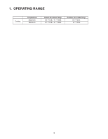
1. OPERATING RANGE Cooling Temperature Maximum Minimum Indoor Air Intake Temp. 95 °F D.B. / 71 °F W.B. 67 °F D.B. / 57 °F W.B. Outdoor Air Intake Temp. 115 °F D.B. 67 °F D.B. 5 - Sanyo CM1972 | Service Manual - Page 6
are based on the following unit combination. For other combination unit, please refer to the "Unit Combination Tables" in this manual. Indoor Unit : KMS0972 3units Outdoor Unit : CM1972 1unit 2. Rating conditions are: Cooling : Indoor air temp. 80°F D.B./ 67°F W.B. Outdoor air temp. 95°F D.B./ 75 - Sanyo CM1972 | Service Manual - Page 7
are based on the following unit combination. For other combination unit, please refer to the "Unit Combination Tables" in this manual. Indoor Unit : KMS0972 3units Outdoor Unit : CM1972 1unit 2. Rating conditions are: Cooling : Indoor air temp. 80°F D.B./ 67°F W.B. Outdoor air temp. 95°F D.B./ 75 - Sanyo CM1972 | Service Manual - Page 8
.ft (m3) < 230V > 4-Room Multi Outdoor Unit 4 3 230V Single-Phase 60Hz Cooling 25,400 ( 9,800 to 25,400 ) 7.50 ( 2.90 to 7.50 ) 21,400 4,000 1,707 (2,900) 187 to 253 11.3 2,560 98 9.9 16.2 13.0 20 Outdoor Unit Microprocessor Auto (Hi, Me, Lo) DC Twin Rotary (Inverter) R410A / 6.17 (2,800) Electric - Sanyo CM1972 | Service Manual - Page 9
.ft (m3) < 208V > 4-Room Multi Outdoor Unit 4 3 208V Single-Phase 60Hz Cooling 24,400 ( 9,800 to 24,400 ) 7.20 ( 2.90 to 7.20 ) 20,600 3,800 1,707 (2,900) 187 to 253 12.5 2,560 98 9.5 16.2 13.0 20 Outdoor Unit Microprocessor Auto (Hi, Me, Lo) DC Twin Rotary (Inverter) R410A / 6.17 (2,800) Electric - Sanyo CM1972 | Service Manual - Page 10
.ft (m3) < 230V > 4-Room Multi Outdoor Unit 4 4 230V Single-Phase 60Hz Cooling 30,600 ( 9,800 to 30,600 ) 9.00 ( 2.90 to 9.00 ) 25,800 4,800 1,942 (3,300) 187 to 253 12.3 2,800 99 10.9 17.6 17.0 20 Outdoor Unit Microprocessor Auto (Hi, Me, Lo) DC Twin Rotary (Inverter) R410A / 8.38 (3,800) Electric - Sanyo CM1972 | Service Manual - Page 11
are based on the following unit combination. For other combination unit, please refer to the "Unit Combination Tables" in this manual. Indoor Unit : KMS0972 4units Outdoor Unit : CM3172 1unit 2. Rating conditions are: Cooling : Indoor air temp. 80°F D.B./ 67°F W.B. Outdoor air temp. 95°F D.B./ 75 - Sanyo CM1972 | Service Manual - Page 12
F VAC Crankcase Heater Fan Type Q'ty ... Dia. inch (mm) Fan Motor Type Model ... Q'ty No. of Poles Rough Measure RPM (Cool) Nominal Output Coil Resistance (Ambient Temp. 68 °F (20 °C)) W Ohm Safety Device Type Over-Current Protection Over-Heat Protection Run Capacitor Heat Exchanger Coil - Sanyo CM1972 | Service Manual - Page 13
F VAC Crankcase Heater Fan Type Q'ty ... Dia. inch (mm) Fan Motor Type Model ... Q'ty No. of Poles Rough Measure RPM (Cool) Nominal Output Coil Resistance (Ambient Temp. 68 °F (20 °C)) W Ohm Safety Device Type Over-Current Protection Over-Heat Protection Run Capacitor Heat Exchanger Coil - Sanyo CM1972 | Service Manual - Page 14
Outdoor Unit CM3172 Control PCB Part No. Controls Control Circuit Fuse Compressor Type Compressor Model / Nominal Output Compressor Oil ... Amount Pints (cc) Coil Resistance (Ambient Temp. 68 °F (20 °C)) Ohm Safety Device CT (Peak current cut-off control) Compressor Discharge Temp. - Sanyo CM1972 | Service Manual - Page 15
air temp sensor Outdoor heat exchanger sensor AW / AN sensor BW / BN sensor CW / CN sensor DW / DN sensor Model No. of sensor TKS295B TKS292B TKS292B TKS292B TKS292B TKS292B CM1972 1 1 1 / 1 1 / 1 1 / 1 0 Quantity of Sensor CM2472 1 1 1 / 1 1 / 1 1 / 1 1 / 1 Resistance (k ohm) 40 35 30 25 - Sanyo CM1972 | Service Manual - Page 16
3. DIMENSIONAL DATA Outdoor Unit CM1972 11-17/32 23-15/16 5-11/32 15/32 1-3/8 ID:23/32 2-ID:15/16 12-19/32(320) 13-19/32 14-17/32 35-7/16(900) 2-15/16 Wide tube service valve dia.3/8" (9.52) × 3 Narrow tube service valve dia.1/4" (6.35) × 3 29-1/8(740) 4-7/16 2-15/16 2-3/4 5-29/32 - Sanyo CM1972 | Service Manual - Page 17
Outdoor Unit CM2472 11-17/32 23-15/16 5-11/32 15/32 1-3/8 ID:23/32 2-ID:15/16 12-19/32(320) 13-19/32 14-17/32 35-7/16(900) 2-15/16 Wide tube service valve dia.3/8" (9.52) × 3 Narrow tube service valve dia.1/4" (6.35) × 4 Wide tube service valve dia.1/2" (12.70) × 1 4-7/16 2-15/16 - Sanyo CM1972 | Service Manual - Page 18
Outdoor Unit CM3172 11-17/32 23-15/16 5-11/32 15/32 1-3/8 ID:23/32 2-ID:15/16 12-19/32(320) 13-19/32 14-17/32 35-7/16(900) 2-15/16 Wide tube service valve dia.3/8" (9.52) × 2 Narrow tube service valve dia.1/4" (6.35) × 4 Wide tube service valve dia.1/2" (12.70) × 2 35-1/32(890) 4-7/16 - Sanyo CM1972 | Service Manual - Page 19
Service valve on narrow tube CN Electric expansion valve M BN M AN M Strainer Header Cooling cycle Insulation of Refrigerant Tubing IMPORTANT Because capillary tubing is used in the outdoor unit, both the wide and narrow tubes of this air conditioner become cold. To prevent heat - Sanyo CM1972 | Service Manual - Page 20
Service valve on narrow tube DN Electric expansion valve M CN M BN M AN M Strainer Header Heat exchanger Compressor Cooling cycle Insulation of Refrigerant Tubing IMPORTANT Because capillary tubing is used in the outdoor unit, both the wide and narrow tubes of this air conditioner - Sanyo CM1972 | Service Manual - Page 21
Service valve on narrow tube DN Electric expansion valve M CN M BN M AN M Strainer Header Heat exchanger Compressor Cooling cycle Insulation of Refrigerant Tubing IMPORTANT Because capillary tubing is used in the outdoor unit, both the wide and narrow tubes of this air conditioner - Sanyo CM1972 | Service Manual - Page 22
Lo fan 174 (1.2) 160 (1.1) Hi fan HH fan Indoor air temp. 86°F 80°F 75°F (30°C) (27°C) (24°C) Low pressure at wide tube service valve psig (MPaG) 146 (1.0)77 86 95 104 (25) (30) (35) (40) Outdoor air temperature °F (°C) (2) Operating current performance chart Lo fan 5 Hi - Sanyo CM1972 | Service Manual - Page 23
tube service valve psig (MPaG) Outdoor Unit CM1972 Indoor Unit KMS0972 × 1 Cooling Characteristics (RH : 46%, Indoor fan speed : High fan) (230V, 60Hz) (1) Low pressure performance chart 188 (1.3) Lo fan Hi fan HH fan 174 (1.2) 160 (1.1) Indo87o05r°°FFair((22te74m°°CCp)). 86°F (30°C) 146 - Sanyo CM1972 | Service Manual - Page 24
16) 57.2(14) 53.6(12) 50.0(10) Indoor air temp. 86°F (30°C) 80°F (27°C) 75°F (24°C) 46.4( 8) 77 86 95 104 (25) (30) (35) (40) Outdoor air temperature °F (°C) NOTE • This performance chart shows operation of a single wall-mounted indoor unit. The performance chart will vary depending on - Sanyo CM1972 | Service Manual - Page 25
at wide tube service valve psig (MPaG) Outdoor Unit CM1972 Indoor Unit KMS1872 × 1 Cooling Characteristics (RH : 46%, Indoor fan speed : High fan) (230V, 60Hz) (1) Low pressure performance chart 174 (1.2) 160 (1.1) Lo fan HH fan Hi fan Indo8o0r°aFir(2te7m°Cp). 86°F (30°C) 75°F (24°C) 146 - Sanyo CM1972 | Service Manual - Page 26
tube service valve psig (MPaG) 5-1-2. Temperature Charts (CM2472) Outdoor Unit CM2472 Indoor Unit KMS0772 × 1 Cooling Characteristics (RH : 46%, Indoor fan speed : High fan) (230V, 60Hz) (1) Low pressure performance chart 188 (1.3) Lo fan 174 (1.2) 160 (1.1) Hi fan HH fan Indoor air temp - Sanyo CM1972 | Service Manual - Page 27
tube service valve psig (MPaG) Outdoor Unit CM2472 Indoor Unit KMS0972 × 1 Cooling Characteristics (RH : 46%, Indoor fan speed : High fan) (230V, 60Hz) (1) Low pressure performance chart 188 (1.3) Lo fan Hi fan HH fan 174 (1.2) 160 (1.1) In87d05o°°FFor((2a27i4r°°tCCe)m) p. 86°F (30°C) 146 - Sanyo CM1972 | Service Manual - Page 28
at wide tube service valve psig (MPaG) Outdoor Unit CM2472 Indoor Unit KMS1272 × 1 Cooling Characteristics (RH : 46%, Indoor fan speed : High fan) (230V, 60Hz) (1) Low pressure performance chart 174 (1.2) Lo fan 160 (1.1) Hi fan HH fan In87d05o°°oFFr((a22i74r °°tCCem)) p. 86°F (30°C) 146 - Sanyo CM1972 | Service Manual - Page 29
pressure at wide tube service valve psig (MPaG) Outdoor Unit CM2472 Indoor Unit KMS1872 × 1 Cooling Characteristics (RH : 46%, Indoor fan speed : High fan) (230V, 60Hz) (1) Low pressure performance chart 174 (1.2) Lo fan 160 (1.1) HH fan Hi fan Indoor air temp. 86°F (30°C) 80°F 75°F (27 - Sanyo CM1972 | Service Manual - Page 30
wide tube service valve psig (MPaG) Outdoor Unit CM2472 Indoor Unit KMS2472 × 1 Cooling Characteristics (RH : 46%, Indoor fan speed : High fan) (230V, 60Hz) (1) Low pressure performance chart 174 (1.2) Lo fan 160 (1.1) 146 (1.0) Hi fan HH fan Indoor air temp. 86°F 80°F (30°C) (27°C) 75 - Sanyo CM1972 | Service Manual - Page 31
Outdoor Unit CM3172 Indoor Unit KMS0772 × 1 Cooling Characteristics (RH : 46%, Indoor fan speed : High fan) (230V, 60Hz) (1) Low pressure performance chart 174 (1.2) Lo fan Hi fan Hi fan HH fan Low pressure at wide tube service valve psig (MPaG) 146 (1.0) 118 (0.8) Indoor air temp. 86°F (30 - Sanyo CM1972 | Service Manual - Page 32
Outdoor Unit CM3172 Indoor Unit KMS0972 × 1 Cooling Characteristics (RH : 46%, Indoor fan speed : High fan) (230V, 60Hz) (1) Low pressure performance chart 174 (1.2) Lo fan Hi fan Hi fan HH fan Low pressure at wide tube service valve psig (MPaG) 146 (1.0) 118 (0.8) Indoor air temp. 86°F (30 - Sanyo CM1972 | Service Manual - Page 33
Outdoor Unit CM3172 Indoor Unit KMS1272 × 1 Cooling Characteristics (RH : 46%, Indoor fan speed : High fan) (230V, 60Hz) (1) Low pressure performance chart 174 (1.2) Lo fan Hi fan Hi fan HH fan Low pressure at wide tube service valve psig (MPaG) 146 (1.0) 118 (0.8) Indoor air temp. 86°F (30 - Sanyo CM1972 | Service Manual - Page 34
Outdoor Unit CM3172 Indoor Unit KMS1872 × 1 Cooling Characteristics (RH : 46%, Indoor fan speed : High fan) (230V, 60Hz) (1) Low pressure performance chart 174 (1.2) Lo fan Hi fan Low pressure at wide tube service valve psig (MPaG) 146 (1.0) 118 (0.8) Indoor air temp. 86°F 80°F (30°C) (27 - Sanyo CM1972 | Service Manual - Page 35
Outdoor Unit CM3172 Indoor Unit KMS2472 × 1 Cooling Characteristics (RH : 46%, Indoor fan speed : High fan) (230V, 60Hz) (1) Low pressure performance chart 174 (1.2) Lo fan Hi fan 146 (1.0) Low pressure at wide tube service valve psig (MPaG) 118 (0.8) 90 (0.6)77 (25) Indoor air temp. 86°F ( - Sanyo CM1972 | Service Manual - Page 36
19,010 22,080 6,670 9,760 12,840 15,760 18,840 21,600 6,330 9,410 12,500 15,410 18,500 20,590 5,980 8,900 Capacity (BTU/h) SHC : Sensible Heat Capacity (BTU/h) NOTE 1. Rating conditions (#) : Indoor Unit Entering Air Temp. 80 °F (26.7 °C) D.B. / 67 °F (19.4 °C) W.B. : Outdoor Ambient Temp - Sanyo CM1972 | Service Manual - Page 37
13,700 16,610 5,470 8,560 11,640 14,560 TC : Total Cooling Capacity (BTU/h) SHC : Sensible Heat Capacity (BTU/h) NOTE 1. Rating conditions (#) : Indoor Unit Entering Air Temp. 80 °F (26.7 °C) D.B. / 67 °F (19.4 °C) W.B. : Outdoor Ambient Temp. 95 °F (35 °C) D.B. 2. Above data does not take Freeze - Sanyo CM1972 | Service Manual - Page 38
Outdoor Unit : CM3172 Indoor Unit : KMS0972 × 4 Power Supply : 230V Single Phase 60Hz < Cooling Capacity > RATING CAPACITY: INDOOR ENT. TEMP. °F (°C) W.B. D.B. 30,600 BTU/h 65 (18.3) TC 31,170 AIR FLOW RATE: OUTDOOR AMBIENT TEMP. °F (°C) 75 (23.9) 85 (29.4) 95 (35.0) 30,000 28,730 28, - Sanyo CM1972 | Service Manual - Page 39
BLK BLK OUTDOOR THERMISTOR AW THERMISTOR YEL YEL YEL YEL AN THERMISTOR L2 L1 POWER SUPPLY 6. ELECTRICAL DATA 6-1. Electric Wiring Diagrams Outdoor Unit CM1972 To avoid electrical shock hazard, be sure to WARNING disconnect power before checking, servicing and/or cleaning any electrical parts. 8FA2 - Sanyo CM1972 | Service Manual - Page 40
YEL YEL BLK BLK OUTDOOR THERMISTOR AW THERMISTOR YEL YEL YEL YEL AN THERMISTOR L2 L1 POWER SUPPLY UNIT TO INDDOR UNIT UNIT UNIT UNIT To avoid electrical shock hazard, be sure to WARNING disconnect power before checking, servicing and/or cleaning any electrical parts. 8FA2-5257-59000-1 40 - Sanyo CM1972 | Service Manual - Page 41
YEL CN THERMISTOR ORG RED YEL BLK GRY YEL YEL YEL YEL YEL DN THERMISTOR CW THERMISTOR YEL YEL 12345 UNIT UNIT UNIT UNIT TO INDDOR UNIT To avoid electrical shock hazard, be sure to WARNING disconnect power before checking, servicing and/or cleaning any electrical parts. Outdoor Unit CM3172 - Sanyo CM1972 | Service Manual - Page 42
are an example of CM3172 and the values are different from the other models. INITIAL Control/conditions Breaker is ON. The ON/OFF operation button on the remote controller is pressed. Unit operation Explanation Power is supplied to the indoor and outdoor unit control circuits, however the - Sanyo CM1972 | Service Manual - Page 43
with no changes. Stop Approximately 3 minutes later, if the temperature of the indoor heat exchanger is adove 46.4 °F, the system returns to its original conditions. All indicator lamps turn OFF. The indoor and outdoor units stop. Operation is restarted within 4 hours (only when AUTO mode is - Sanyo CM1972 | Service Manual - Page 44
outdoor temperatures are high, the current peak cut-off activates, stopping any increases in frequency. Operating frequency is stabilized in order to maintain a comfortable environment. Operates to effectively dehumidify the air while not excessively reducing the indoor temperature. The indoor unit - Sanyo CM1972 | Service Manual - Page 45
current in parentheses are an example of CM3172 and the values are different from the other models. 7-2-1. Current Control The operating current exceeded. (May operate when sudden voltage fluctuations occur. Indicates trouble.) (1) Automatic frequency control The operating frequency is reduced - Sanyo CM1972 | Service Manual - Page 46
Hz increase prohibit (16) (15.6) 0 Hz reduction Hz increase prohibit (30) Frequency (Hz) 7-2-2. Low Start Current Operation starts at (8 Hz), and fluorescent lights or television screens that occurs when ordinary A/C units start. 7-2-3. Compressor Temperature Control To protect the compressor - Sanyo CM1972 | Service Manual - Page 47
capacitors are used inside the outdoor unit controller (inverter). They retain an electrical charge (charging voltage DC 311 V) even after the power is turned OFF, and some time is required for the charge to dissipate. Be careful not to touch any electrified parts before the control circuit board - Sanyo CM1972 | Service Manual - Page 48
is a sensor failure in the outdoor unit, the 4 error monitor lamps on the outdoor control circuit board will indicate the nature of the trouble. : ON : OFF Error Monitor Lamp ERR0 ERR1 ERR2 ERR3 Error Contents Sensor for compressor discharge temp Sensor for heat excharge temp Sensor for branch - Sanyo CM1972 | Service Manual - Page 49
8-3. Checking the Outdoor System 8-3-1. Checking the outdoor unit No. Work procedure 1 • Apply 220 V AC between terminals L1 and L2 on the outdoor unit terminal plate. 2 • Short-circuit the T-RUN terminal to the COM terminal of TEST/T-RUN terminals. Check items (unit operation) • The LED (red) - Sanyo CM1972 | Service Manual - Page 50
Trouble Diagnosis of Each Part 8-4-1. Problems of Each Part and Inspection Points For details about the inspection points, refer to the Inspection Points for Each Part. Problems Indoor unit Inspection points Outdoor unit Others No. of Inspection Points for Each part Indoor unit Indoor unit - Sanyo CM1972 | Service Manual - Page 51
Problems Indoor unit Inspection points Breaker Refrigerant gas pressure Outdoor unit Others No. of Inspection Points for Each part (8) (9) 8-4-2. Inspection Points for Each Part (1) Outdoor thermistor) Check that the senseor is securely contained in the thermostart holder. (5) Coil thermistor - Sanyo CM1972 | Service Manual - Page 52
Use a multi-meter to Model No. Sequence CM1972 MV0 MV1 MV2 CM2472 CM3172 part is normal. Check elsewhere. Use the special service magnet and rotate 5 revolutions clockwise to fully close the valve. Then start the unit manually checked the electric expansion valve, be sure to reapply the outdoor - Sanyo CM1972 | Service Manual - Page 53
the temperatures of the A/C intake air and discharge air. Compare the values with the There is little condensation on the indoor heart exchanger, which overall appears dry the change is small, then the problem may not be refrigerant shortage. The problem may be a blockage of the refrigerant - Sanyo CM1972 | Service Manual - Page 54
This outdoor DC fan motor contains an internal control PCB. Therefore, it is not possible to measure the coil resistance, and the following procedure should be used to check the motor. Perform the trouble diagnosis by Test Run mode described on Installation Instructions of indoor unit. Important - Sanyo CM1972 | Service Manual - Page 55
SERVICING UNIT of the air conditioner may be degraded because of a change in composition of the remaining refrigerant. Therefore, do not add new refrigerant. Instead, recover the remaining refrigerant with the refrigerant recovery unit of the air conditioner will be -type units, which - Sanyo CM1972 | Service Manual - Page 56
9-2. Checklist before Servicing Use a clutch-type flare tool for R410A or the with caps or tape prior to installation. Never use 0.0276" (0.7 mm)-thick copper tubing or tubing which is less than 0.0315" (0.8 mm) in thickness, since air conditioners with R410A are subject to higher pressure - Sanyo CM1972 | Service Manual - Page 57
the flare portions to improve the sealing of tubing. The following is the HAB oil generally used: Esso: ZERICE S32 NOTE For details on tubing installation procedures, refer to the installation manuals attached to the indoor unit and outdoor unit. 57 - Sanyo CM1972 | Service Manual - Page 58
inside the unit should not be released to the atmosphere, but recovered using the refrigerant recovery unit for R410A. solenoid valve-installed vacuum pump so that even if power is cut off in the middle of evacuation of air due to a power interruption, the valve will prevent the pump oil from - Sanyo CM1972 | Service Manual - Page 59
service port of the wide tube service valve. The proper amount is listed on the unit's nameplate. When the entire amount cannot be charged all at once, charge gradually while operating the unit to charge the air conditioning unit. Example: In case of charging refrigerant to a unit requiring 1.68 - Sanyo CM1972 | Service Manual - Page 60
utilizing substitution with nitrogen (N2) in the refrigerant circuit of the unit. Leave ends of tubes open during welding. (1) Detect leaks OK valve-installed vacuum pump so that even if power is cut off in the middle of evacuation of air due to a power interruption, the valve will prevent the pump - Sanyo CM1972 | Service Manual - Page 61
of refrigerant as stated in this service manual or the installation manual that came with the indoor unit. Charge additional refrigerant in liquid state only. CAUTION Never charge additional refrigerant if refrigerant is leaking from the unit. Follow instructions given in "9-6. In Case Refrigerant - Sanyo CM1972 | Service Manual - Page 62
APPENDIX A INSTALLATION INSTRUCTIONS CM1972 CM2472 CM3172 (II-852-6-4190-214-00-3) A-1 - Sanyo CM1972 | Service Manual - Page 63
INSTALLATION INSTRUCTIONS - Inverter Multi Split System Air Conditioner - COOL/DRY Model This air conditioner uses the new refrigerant R410A. NOTE Refrigerant service valve size = 5/16" Contents Page IMPORTANT! Please Read Before Starting 2 Model Combinations Combine indoor and outdoor units - Sanyo CM1972 | Service Manual - Page 64
and abnormal vibration. ...In an Area with High Winds Securely anchor the outdoor unit down with bolts and a metal frame. Provide a suitable air baffle. ...In a Snowy Area (for Heat Pump-type Systems) Install the outdoor unit on a raised platform that is higher than drifting snow. Provide snow vents - Sanyo CM1972 | Service Manual - Page 65
where and how to install the air conditioning system. Please read over the entire set of instructions for the indoor and outdoor units and make sure all accessory parts listed are with the system before beginning. If the electric wiring diagram does not appear in this manual, please check for the - Sanyo CM1972 | Service Manual - Page 66
a total tubing length (L1+L2+L3, L1+L2+L3+L4) from the outdoor unit as detailed in Table 3 and Fig. 3a. CAUTION For stable operation of the Indoor unit Wall air conditioner, do not install wall-mounted type indoor units less than 5' (1.5 m) from floor level. Minimum height from floor level - Sanyo CM1972 | Service Manual - Page 67
system, or intercom. Electrical noise from any of these sources may affect operation. G install in a sturdy manner to avoid increased operating noise. Table 3 Model Max. Allowable Tubing Length per unit ) 200 (L1+L2+L3+L4) 50 0.22 CM3172/CLM3172 100 150 (L1+L2+L3+L4) 230 Service Manual. 5 - Sanyo CM1972 | Service Manual - Page 68
different sizes (3/8"(9.52mm) 1/2"(12.70mm)) Supplied Reducer Indoor unit (KMS0772,KMS0972,KMS1272) (KMS0772,KMS0972,KMS1272) (KMS1872) Fig. 4b (2) Connecting indoor unit for CM2472/CLM2472 (A) Outdoor unit D 3/8"(9.52mm) 3/8"(9.52mm) C 1/4"(6.35mm) 3/8"(9.52mm) 3/8"(9.52mm) B 1/4"(6.35mm - Sanyo CM1972 | Service Manual - Page 69
,KMS0972,KMS1272) (KMS0772,KMS0972,KMS1272) (KMS0772,KMS0972,KMS1272) (KMS2472) Fig. 4e (D) Outdoor unit D 3/8"(9.52mm) C 3/8"(9.52mm) B 3/8"(9.52mm) A 1/2"(12.70mm) 3/8"(9.52mm) Indoor unit (KMS0772,KMS0972,KMS1272) 1/4"(6.35mm) 3/8"(9.52mm) (KMS0772,KMS0972,KMS1272) 1/4"(6.35mm) 1/2"(12 - Sanyo CM1972 | Service Manual - Page 70
(3) Connecting indoor unit for CM3172/CLM3172 (A) Outdoor unit D 3/8"(9.52mm) C 3/8"(9.52mm) B 1/2"(12.70mm) A 1/2"(12.70mm) 3/8"(9.52mm) 1/4"(6.35mm) 3/8"(9.52mm) 1/4"(6.35mm) 3/8"(9.52mm) 1/4"(6.35mm) 3/8"(9.52mm) 1/4"(6.35mm) Indoor unit (KMS0772,KMS0972,KMS1272) (KMS0772,KMS0972,KMS1272) ( - Sanyo CM1972 | Service Manual - Page 71
Reducer Fig. 4j (E) Outdoor unit D 3/8"(9.52mm) 3/8"(9.52mm) C 1/4"(6.35mm) 3/8"(9.52mm) 3/8"(9.52mm) B 1/4"(6.35mm) 1/2"(12.70mm) 1/2"(12.70mm) A 1/4"(6.35mm) 5/8"(15.88mm) 1/2"(12.70mm) 1/4"(6.35mm) Flare 1/2"(12.70mm) Union 5/8"(15.88mm) Indoor unit (KMS0772,KMS0972,KMS1272 - Sanyo CM1972 | Service Manual - Page 72
), baffle plates must be installed on the outdoor unit. (Fig. 5f) This unit is designed so that the fan of the outdoor unit runs at low speed when the air conditioner is operated at low outdoor air temperatures. When the outdoor unit is exposed to strong wind, the system pressure drops because of - Sanyo CM1972 | Service Manual - Page 73
Air Discharge Dimensions A B C D E F Model CLM1972, 2472, (inch) 22-1/16 23-1/32 13-25/32 5-29/32 19-9/32 1-3/8 3172 Parts required (field supply except for screws) Air Intake Baffle Item Q'ty Remarks Baffle plate 1 Screw 5/32 × 15/32" (4 × 12 mm) tapping 2 Attached to outdoor unit - Sanyo CM1972 | Service Manual - Page 74
In order to prevent contact of the bolts and heat exchanger and other parts inside the unit, install the windbaffle using bolts from inside the unit and fasten the bolts with nuts from outside the unit. G When the windbaffle is installed on the unit, the unit has higher wind resistance. In order to - Sanyo CM1972 | Service Manual - Page 75
12-19/32 13-19/32 14-17/32 2-5. Outer Dimensions of Outdoor Unit (1) CM1972/CLM1972 23-15/16 5-11/32 15/32 A A 35-7/16 (900) 2-29/32 Service valve on narrow tube side (Outer diameter 1/4"(6.35)) Service valve on wide tube side (Outer diameter 3/8"(9.52)) 2-3/4 29-1/8 (740) 2-3/4 2-15/16 - Sanyo CM1972 | Service Manual - Page 76
2-6. Diagram of Outdoor Unit Installation Never install only a single indoor unit. Be sure to connect indoor and outdoor units only in combinations that are listed in the catalog or in the combination table that was provided with the outdoor unit. (Use caution. Connecting any other model may result - Sanyo CM1972 | Service Manual - Page 77
Installation Process 3-1. Embedding the Tubing and Wiring G Do not connect tubes to locations that are embedded. G Be sure to bind refrigerant tubing and inter-unit split system air conditioners employ the flaring method to connect refrigerant tubes which run between indoor and outdoor units. In - Sanyo CM1972 | Service Manual - Page 78
540 lbs·in (490 - 610 kgf·cm) Approx. 590 - 710 lbs·in (680 - 820 kgf·cm) Union Flare nut Fig. 13 Service valve on D narrow tube side C B A Service valve on wide tube side Fig. 14 16 Apply the provided labels to the indoor and outdoor unit tubing connectors to prevent errors in connections. - Sanyo CM1972 | Service Manual - Page 79
Be sure to match refrigerant tubing and electric wiring between indoor and outdoor units. For more details, refer to "Tubing Check Control" in the Technical & Service Manual. 3-6. Insulation of Refrigerant Tubing I M P O R TA N T To prevent heat loss and wet floors due to dripping of condensation - Sanyo CM1972 | Service Manual - Page 80
recharging or performing other servicing, use the special charging hose and manifold gauge. Perform the air purge for tubes A, B, C, and D. Use the same procedures for all tubes. (1) Check that each tube (both narrow and wide tubes) between the indoor and outdoor units have been properly connected - Sanyo CM1972 | Service Manual - Page 81
Table 5 Required time for evacuation when capacity of 100 liter/h vacuum pump is used 20 min. or more NOTE The required time in the the wide tube service port slightly to release the pressure. Then, remove the hose. (10) Leak test all joints at the tubing (both indoor and outdoors) with liquid soap - Sanyo CM1972 | Service Manual - Page 82
winter, the outdoor unit may stop after 5 - 10 minutes of operation. This is in order to protect the indoor unit heat exchanger from freezing and does not indicate a problem. (4) Disconnect the manifold gauge and the inter-unit tubes, and attach the caps and flare nuts. At this point, pump-down is - Sanyo CM1972 | Service Manual - Page 83
system diagram. Wrong wiring may cause the unit to misoperate or become damaged. (5) Do not allow wiring to touch the refrigerant tubing, compressor, or any moving parts carrying out the installation. Table 6 ANSI/NFPA70. Table 6 Model AWG CM1972 / CLM1972 CM2472 / CLM2472 CM3172 / CLM3172 Max. - Sanyo CM1972 | Service Manual - Page 84
the outdoor unit and respective indoor units A - D. CAUTION WARNING G To avoid the risk of electric shock, each air conditioner unit must be grounded. G For the installation of a grounding device, please observe local electrical codes. G Grounding is necessary, especially for units using inverter - Sanyo CM1972 | Service Manual - Page 85
instructions "How to connect wiring to the terminal" and fasten the wire securely tight with the fixing screw of the terminal plate. How to connect wiring to the terminal a) For Indoor Unit screwdriver. b) For Outdoor Unit I For solid core screw using a screwdriver. (Fig. 30) 23 Strip 15/16" (25 - Sanyo CM1972 | Service Manual - Page 86
Wiring Instructions for the Outdoor Unit CAUTION G Be sure to correctly align inter-unit cables A, B, C and D. Outdoor unit A Terminal board 1 2 Indoor unit A 1 2 3 4 5 6 7 8 9 10 11 12 A is the indoor unit with refrigerant tubing that is connected to service valve A (top) of the outdoor unit - Sanyo CM1972 | Service Manual - Page 87
connections are correct as shown in the wiring system diagram on panel side. (5) Be sure to ground the unit according to your local codes. 6. Test Run Performing a test run G Refer to the test run procedures in the indoor unit installation manual. G Perform the test run separately for each connected - Sanyo CM1972 | Service Manual - Page 88
) 4P terminal is located on the indoor unit PCB. If a HA device will be used, connect it to this terminal. 8. Installation Check Sheet The strength of the installation location is sufficient to support the A/C weight. The indoor and outdoor units are installed level and vertically. The power and - Sanyo CM1972 | Service Manual - Page 89
CM1972 4-Room Outdoor Unit Combination Table CM2472 4-Room Outdoor Unit Combination Table CM3172 Remarks OI-852-6-4180-818-00-4 OI-852-6-4180-819-00-4 OI-852-6-4180-820-00-4 NOTE Be sure to operate the air conditioning system only when 2 or more indoor units have been installed. If operated - Sanyo CM1972 | Service Manual - Page 90
the indoor units installed must not be operated concurrently under any circumstances. Otherwise, the air conditioner may not run properly and trouble may occur. Example: When 3 indoor units are connected at 230V If the following holds true Rated cooling capacity of CM1972 outdoor unit: C=19700 (BTU - Sanyo CM1972 | Service Manual - Page 91
Table 1 Single-room Operation 2-room Operation 3-room Operation Indoor Unit Capacity (BTU/h) Indoor Unit Combination COOLING Room Room Room Total Performance A B 35700 6567 6567 6567 19700 ( 9800 - 19700 ) The table lists the wall-mounted type of indoor units as representative models. -2- - Sanyo CM1972 | Service Manual - Page 92
Table 2 Single-room Operation 2-room Operation 3-room Operation Indoor Unit Capacity (BTU/h) Indoor Unit Combination COOLING Room Room Room Total Performance A B 35700 6567 6567 6567 19700 ( 9800 - 19700 ) The table lists the wall-mounted type of indoor units as representative models. -3- - Sanyo CM1972 | Service Manual - Page 93
the indoor units installed must not be operated concurrently under any circumstances. Otherwise, the air conditioner may not run properly and trouble may occur. Example: When 4 indoor units are connected at 230V If the following holds true Rated cooling capacity of CM2472 outdoor unit: C=25400 (BTU - Sanyo CM1972 | Service Manual - Page 94
of 4 indoor units prohibited) This multi outdoor unit allows up to four indoor units to be connected. However, all four indoor units must not be operated concurrently. Otherwise, the air conditioner may not run properly. Up to three indoor units may be operated concurrently. The table lists the - Sanyo CM1972 | Service Manual - Page 95
of 4 indoor units prohibited) This multi outdoor unit allows up to four indoor units to be connected. However, all four indoor units must not be operated concurrently. Otherwise, the air conditioner may not run properly. Up to three indoor units may be operated concurrently. The table lists the - Sanyo CM1972 | Service Manual - Page 96
the indoor units installed must not be operated concurrently under any circumstances. Otherwise, the air conditioner may not run properly and trouble may occur. Example: When 4 indoor units are connected at 230V If the following holds true Rated cooling capacity of CM3172 outdoor unit: C=30600 (BTU - Sanyo CM1972 | Service Manual - Page 97
indoor units > Voltage Rating : 230V 60Hz CM3172 (Rated cooling capacity at 230V: 30600 BTU/h) NOTE 7500 : KMS0772 9000 : KMS0972 11900 : KMS1272 17500 : KMS1872 24200 : KMS2472 Table 1 Indoor Unit 9800 - 30600 ) The table lists the wall-mounted type of indoor units as representative models. -2- - Sanyo CM1972 | Service Manual - Page 98
CM3172 (Rated cooling capacity at 208V: 28600 BTU/h) NOTE 7500 : KMS0772 9000 : KMS0972 11900 : KMS1272 17500 : KMS1872 24200 : KMS2472 Table 2 Indoor Unit - 28600 ) 28600 ( 9800 - 28600 ) 28600 ( 9800 - 28600 ) The table lists the wall-mounted type of indoor units as representative models. -3- - Sanyo CM1972 | Service Manual - Page 99
SANYO Commercial Solutions A Division of SANYO North America Corporation 1300 Michael Drive, Suite A Wood Dale, IL 60191, U.S.A. Sanyo Canada Inc. 1-300 Applewood Crescent, Concord, Ontario L4K 5C7, CANADA Oct. / 2008 (T)
-
 1
1 -
 2
2 -
 3
3 -
 4
4 -
 5
5 -
 6
6 -
 7
7 -
8
-
9
-
10
-
11
-
12
-
13
-
14
-
15
-
16
-
17
-
18
-
19
-
20
-
21
-
22
-
23
-
24
-
25
-
26
-
27
-
28
-
29
-
30
-
31
-
32
-
33
-
34
-
35
-
36
-
37
-
38
-
39
-
40
-
41
-
42
-
43
-
44
-
45
-
46
-
47
-
48
-
49
-
50
-
51
-
52
-
53
-
54
-
55
-
56
-
57
-
58
-
59
-
60
-
61
-
62
-
63
-
64
-
65
-
66
-
67
-
68
-
69
-
70
-
71
-
72
-
73
-
74
-
75
-
76
-
77
-
78
-
79
-
80
-
81
-
82
-
83
-
84
-
85
-
86
-
87
-
88
-
89
-
90
-
91
-
92
-
93
-
94
-
95
-
96
-
97
-
98
-
99
 |
 |
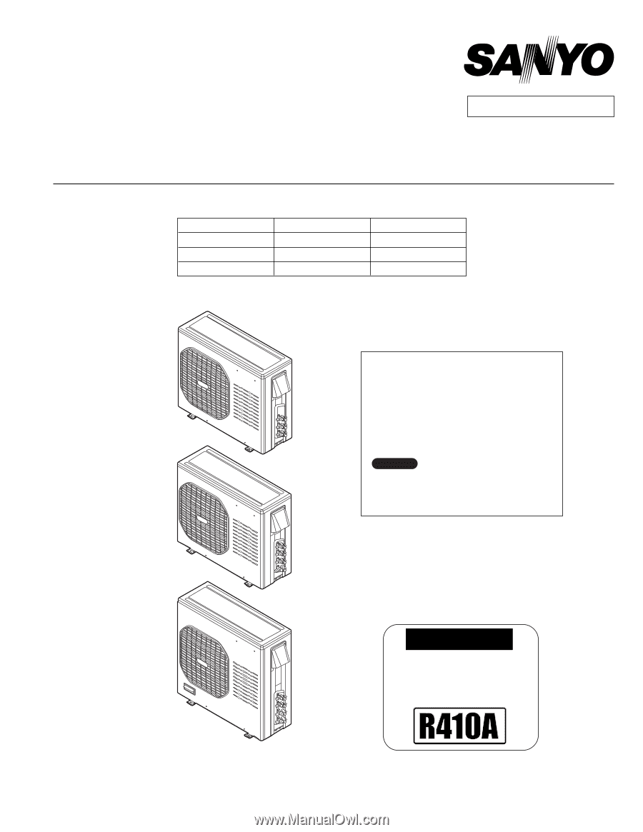
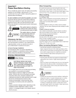
IMPORTANT
These air conditioners employ new
refrigerant R410A.
Pay special attention when
servicing the unit.
●
Wall mounted type
KMS0772
KMS0972
KMS1272
KMS1872
KMS2472
< Applicable Indoor Units >
TECHNICAL & SERVICE MANUAL
OUTDOOR UNIT : CM1972
CM2472
CM3172
DC INVERTER MULTI-SYSTEM AIR CONDITIONER
Destination: North America
Product Code No.
1 852 330 27
1 852 330 28
1 852 330 29
REFERENCE NO.
SM
700666-04
Capacity at 230V
19,700 BTU/h
25,400 BTU/h
30,600 BTU/h
Outdoor Model No.
CM1972
CM2472
CM3172
NOTE
CM1972
CM2472
CM3172
For details about the combination, refer to
"Unit Combination Table" in the Appendix
of this manual.
FILE NO.