Sanyo DP55360 Owners Manual - Page 6
Hdtv Input/output Reference - ethernet
 |
View all Sanyo DP55360 manuals
Add to My Manuals
Save this manual to your list of manuals |
Page 6 highlights
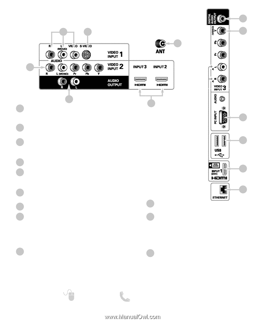
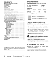
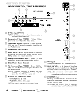
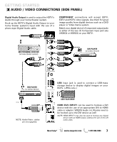
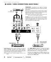
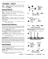
GETTING STARTED HDTV INPUT/OUTPUT REFERENCE 7 2 1 8 HDTV BACK PANEL 6 3 4 1 S-Video Input (VIDEO1) NOTE: An S-Video connection will override a connection to the Video1 (yellow) input jack. 2 Composite AV Input (VIDEO1) - Yellow (Video), plus white and red (Audio) input jacks. 3 Component AV Input (VIDEO2) - Green (Y), blue (Pb), and red (Pr) Video inputs plus the white and red Audio inputs. 4 Stereo Audio Out (L/R) Jacks 5 HDMI (INPUT2 & 3) - An all digital AV interface accepting uncompressed video signals up to 1080p for the best picture possible. 6 Analog / Digital Antenna Input - Connect a 75 OHM cable from an antenna or direct Cable service. 7 Digital Audio Output (Coaxial) 8 AV Component Input (VIDEO3) - Green (Y), blue (Pb), and red (Pr) Video inputs plus the white and red Audio inputs. NOTE: A Composite connection is possible via VIDEO INPUT3 using the Y (VIDEO) jack and the L/R audio jacks. (See Video 3 Setting on page 12.) 9 PC Input and Stereo Audio (Mini) • MONITOR RGB (D-SUB) • AUDIO R/L (Stereo Mini Jack) NOTE: See page 18 for proper PC hookup and setup. 5 9 HDTV SIDE PANEL 10 11 12 10 USB Input View pictures stored in a USB flash drive. 11 HDMI (INPUT1) - An all digital AV interface accepting uncompressed video signals up to 1080p for the very best picture possible. NOTE: A DVI connection is possible via the HDMI INPUT1 (DVI) using an appropriate adapter and the VIDEO3 Audio jacks for sound output. 12 ETHERNET Port Hook up your HDTV to the internet with the use of an appropriate ethernet cable and a correct internet setup. NOTE: Please refer to the cTV Guide for the proper connection to your Local Area Network (LAN). 6 Need help? www.sanyoctv.com 1-877-864-9604
-
 1
1 -
 2
2 -
 3
3 -
 4
4 -
 5
5 -
 6
6 -
 7
7 -
 8
8 -
 9
9 -
 10
10 -
 11
11 -
 12
12 -
13
-
14
-
15
-
16
-
17
-
18
-
19
-
20
-
21
-
22
-
23
-
24
-
25
-
26
-
27
-
28
-
29
-
30
-
31
-
32
-
33
-
34
-
35
-
36
-
37
-
38
-
39
-
40
 |
 |