Sanyo H1340 Operating Instructions - Page 8
Electrical, Connections, I .ii, Caution - ecd
 |
View all Sanyo H1340 manuals
Add to My Manuals
Save this manual to your list of manuals |
Page 8 highlights
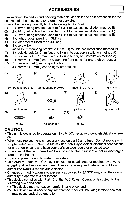
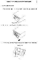
I ELECTRICAL CONNECTIONS I WIRING FOR ECD-HI340 I .II 11111 fkignd ----- 4-speaker System _ _ _ _ , -CB n Front Left i slack) emSpeaker I g n Front Riaht I 1 (Gray/Blacke)m Speake; Ireen) $ @ Rear Left Eew Speaker _ _ _ _ _ _ P-speaker System , ! (White)@& _ _ _ _ _, Left I ; (White/Bla--ck) 8 &= =@SIpeaker , I -(Gray) CB-8 A Riaht I , Speaker j 00 not 1 Connect I I Do not I Connect I +12V Constant Power Supply (yellow) +12V Accessory/Switched (Red) Wire (Black) 111 Power Antenna/Amplifier Turn On (Blue/Red) Caution l DO NOT connect any speaker wires to the metal body or chassis of the vehicle l Connect each speaker wire directly to each speaker terminal l All speaker common (-) wires must remain floating 1 Antenna socket l Insert the plug from the antenna installed in your vehicle into this socket (if your vehicle has a dual antenna system, a dual antenna to single antenna cable adaptor may be required ) 2 +12V Constant Power Supply (Yellow) l Connect this wire to the +12V power terminal which receives power continuously 3 +12V Accessory/Switched (Red) l Connect this wire to the terminal which receives power while the ignition switch is ON or in the ACCESSORY position l If the ignition switch does not have an ACC position, connect this wire to a +12V power terminal which receives power continuously (Same as item 2 ) 4 Ground wire (Black) l Connect this wire to the vehicle chassis 5 Power Antenna/Amplifier Turn On (Blue/Red) l Connect this wire to the control terminal of a Power Antenna or an external amplifier l When not using a Power Antenna or an external amplifier, this wire is not connected 6
-
 1
1 -
2
-
 3
3 -
 4
4 -
 5
5 -
 6
6 -
 7
7 -
 8
8 -
 9
9 -
 10
10 -
 11
11 -
 12
12 -
 13
13 -
14
-
15
-
16
 |
 |
