Sanyo PLC-XU47 Owners Manual - Page 15
Connecting to a Computer, Cables used for connection - audio
 |
View all Sanyo PLC-XU47 manuals
Add to My Manuals
Save this manual to your list of manuals |
Page 15 highlights
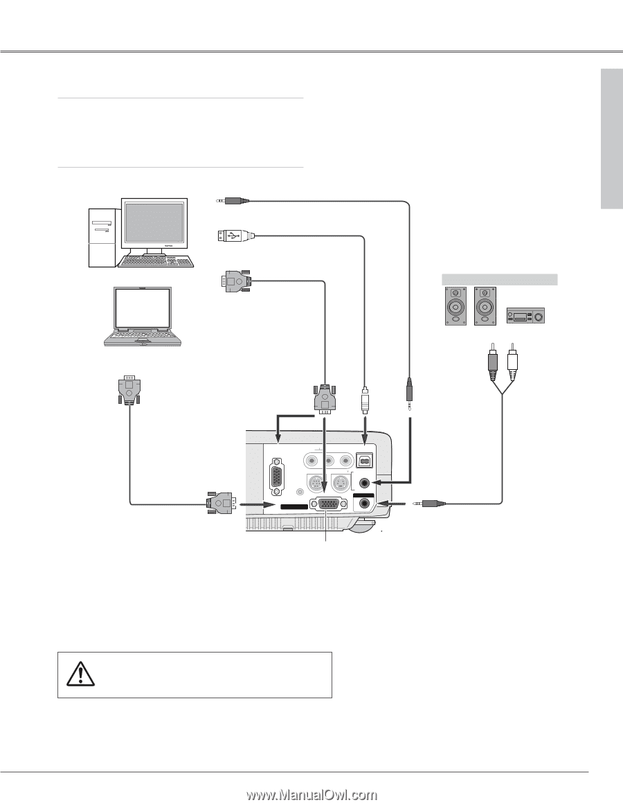
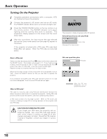
Installation Connecting to a Computer Cables used for connection • VGA Cable (HDB 15 pin) (Only a cable is supplied.) • USB Cable ✽ • Audio Cables (Mini Plug: stereo Not supplied with this projector.) Installation Audio Output Audio cable (stereo) ✽ USB port USB cable ✽ Monitor Output VGA cable Monitor Input External Audio Equipment Audio Input COMPUTER IN 1/ COMPONENT IN (or COMPUTER IN 2/ MONITOR OUT) USB VGA cable ✽ COMPUTER IN 2/ MONITOR OUT CCOOMMPPUUTTEERR IINN 11 / COMPONENDTVIIN- I AUDIO IN R L (MONO) VIDEO USB SERVICE PORT S-VIDEO COMPUTER / / CCOOMMPPOONNEENNTT RESET COMCOPMUPTUETRERIINN 22/ / MCMOONOMNIPTIOTOONRRENOOTUUITNT / AUDIO IN AUDIO OUT (AVRARIAIALBEL)E) This terminal is switcheable. Set up the terminal as either Computer input or Monitor output. (See Page 41.) ✔Note: • If you wish to use Page ed buttons on the remote control, connect USB port of your computer to the USB socket of the projector. (p9 and 42) • When connecting AUDIO OUT to external audio equipment, the projector's built-in speaker is disconnected. Note: When connecting the cable, the power cords of both the projector and the external equipment should be disconnected from AC outlet. COMPUTER/ COMPONENT AUDIO IN AUDIO OUT (stereo) Audio cable ✽ (stereo) 15
-
 1
1 -
2
-
3
-
4
-
5
-
6
-
7
-
8
-
9
-
 10
10 -
 11
11 -
 12
12 -
 13
13 -
 14
14 -
 15
15 -
 16
16 -
 17
17 -
 18
18 -
 19
19 -
 20
20 -
21
-
22
-
23
-
24
-
25
-
26
-
27
-
28
-
29
-
30
-
31
-
32
-
33
-
34
-
35
-
36
-
37
-
38
-
39
-
40
-
41
-
42
-
43
-
44
-
45
-
46
-
47
-
48
-
49
-
50
-
51
-
52
-
53
-
54
-
55
-
56
-
57
-
58
-
59
-
60
 |
 |