Sanyo PLC-XU87 Owners Manual - Page 10
Rear Terminal / Side Terminal, COMPUTER IN 2 /COMPONENT - cable
 |
UPC - 086483065705
View all Sanyo PLC-XU87 manuals
Add to My Manuals
Save this manual to your list of manuals |
Page 10 highlights
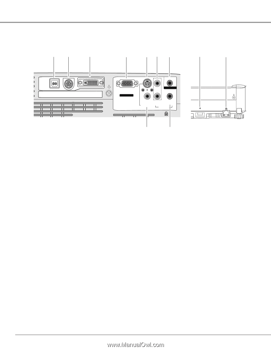
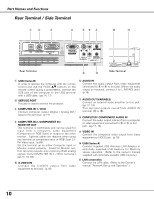
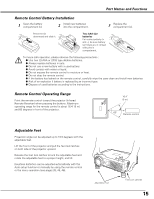
Part Names and Functions Rear Terminal / Side Terminal q w e r ty u !0 !1 (VARIABLE) USB SERVICE PORT COMPUTER IN 1 DVI-I COMPUTER IN 2 / COMPONENT IN MONITOR OUT R AUDIO OUT VIDEO IN L (MONO) COMPUTER / COMPONENT S-VIDEO IN AUDIO IN USB Rear Terminal Side Terminal o i q USB (Series B) In order to operate the computer with the remote control and use the PAGE ed buttons on the remote control during a presentation, connect the USB port of the computer to the USB terminal with a USB cable. (pp.14, 17) w SERVICE PORT This jack is used to service the projector. e COMPUTER IN 1 / DVI-I Connect computer output (Digital / Analog DVI-I type) to this terminal. (p.17) r COMPUTER IN 2 /COMPONENT IN / MONITOR OUT This terminal is switchable and can be used for input from a computer, video equipment (Component or RGB Scart) or output to the other monitor. Optional cables are required when using this terminal as component input or RGB Scart 21Pin Video input. (p.69) Set the terminal up as either Computer input or Monitor output properly. (Used for Monitor out, this terminal outputs only incoming RGB analog signals from COMPUTER IN 1 / DVI-I terminal.) (pp.17, 19, 49) t S-VIDEO IN Connect the S-VIDEO output from video equipment to this jack. (p.18) y AUDIO IN Connect the audio output from video equipment connected to t or o to this jack. (When the audio output is monaural, connect it to L (MONO) jack.) (p.18) u AUDIO OUT(VARIABLE) Connect an external audio amplifier to this jack. (pp.17- 19) This terminal outputs sound from AUDIO IN terminal (y or i). i COMPUTER/ COMPONENT AUDIO IN Connect the audio output (stereo) from a computer or video equipment connected to e or r to this jack. (pp.17, 19) o VIDEO IN Connect the composite video output from video equipment to VIDEO jack. (p.18) !0 USB (Series A) Connect supplied USB Wireless LAN Adapter or optionally supplied USB memory for Memory viewer operation. (Refer to the owner's manual supplied with optionally available USB memory.) !1 LAN connection Connect the LAN cable. (Refer to the Owner's manual "Network Set-up and Operation".) 10
-
 1
1 -
2
-
3
-
4
-
 5
5 -
 6
6 -
 7
7 -
 8
8 -
 9
9 -
 10
10 -
 11
11 -
 12
12 -
 13
13 -
 14
14 -
 15
15 -
16
-
17
-
18
-
19
-
20
-
21
-
22
-
23
-
24
-
25
-
26
-
27
-
28
-
29
-
30
-
31
-
32
-
33
-
34
-
35
-
36
-
37
-
38
-
39
-
40
-
41
-
42
-
43
-
44
-
45
-
46
-
47
-
48
-
49
-
50
-
51
-
52
-
53
-
54
-
55
-
56
-
57
-
58
-
59
-
60
-
61
-
62
-
63
-
64
-
65
-
66
-
67
-
68
-
69
-
70
-
71
-
72
-
73
 |
 |