Seagate ST800FM0022 Pulsar Serial ATA Product Manual - Page 20
Electromagnetic immunity
 |
View all Seagate ST800FM0022 manuals
Add to My Manuals
Save this manual to your list of manuals |
Page 20 highlights
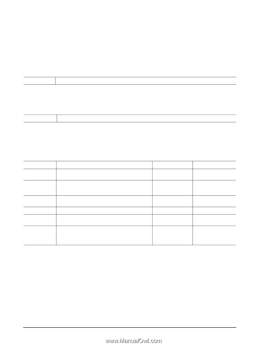
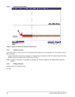
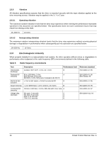
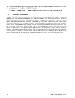
2.9.6 Vibration All vibration specifications assume that the drive is mounted securely with the input vibration applied at the drive mounting screws. Vibration may be applied in the X, Y or Z axis. 2.9.6.1 Operating vibration The maximum random vibration levels that the drive may experience while meeting the performance standards specified in this document are specified below. This specification does not cover connection issues that may result from testing at this level. 20-2000 Hz 16 Grms 2.9.6.2 Nonoperating vibration The maximum random nonoperating vibration levels that the drive may experience without incurring physical damage or degradation in performance when subsequently put into operation are specified below. 20-2000 Hz 16 Grms 2.10 Electromagnetic immunity When properly installed in a representative host system, the drive operates without errors or degradation in performance when subjected to the radio frequency (RF) environments defined in the following table: Table 5: Radio frequency environments Test Electrostatic discharge Radiated RF immunity Electrical fast transient Surge immunity Conducted RF immunity Voltage dips, interrupts Description Contact, HCP, VCP: ± 4 kV; Air: ± 8 kV Performance level B 80 to 1000 MHz, 3 V/m, A 80% AM with 1 kHz sine 900 MHz, 3 V/m, 50% pulse modulation @ 200 Hz ± 1 kV on AC mains, ± 0.5 kV on external I/O B ± 1 kV differential, ± 2 kV common, AC mains B 150 kHz to 80 MHz, 3 Vrms, 80% AM with 1 kHz sine A 0% open, 5 seconds C 0% short, 5 seconds C 40%, 0.10 seconds C 70%, 0.01 seconds B Reference standard EN 61000-4-2: 95 EN 61000-4-3: 96 ENV 50204: 95 EN 61000-4-4: 95 EN 61000-4-5: 95 EN 61000-4-6: 97 EN 61000-4-11: 94 14 Pulsar Product Manual, Rev. A
-
 1
1 -
2
-
3
-
4
-
5
-
6
-
7
-
8
-
9
-
10
-
11
-
12
-
13
-
14
-
 15
15 -
 16
16 -
 17
17 -
 18
18 -
 19
19 -
 20
20 -
 21
21 -
 22
22 -
 23
23 -
 24
24 -
 25
25 -
26
-
27
-
28
-
29
-
30
-
31
-
32
-
33
-
34
-
35
-
36
-
37
-
38
-
39
-
40
-
41
-
42
-
43
-
44
-
45
-
46
-
47
-
48
-
49
-
50
 |
 |