Seagate ST800FM0022 Pulsar Serial ATA Product Manual - Page 26
Configuring the drive, Serial ATA cables and connectors
 |
View all Seagate ST800FM0022 manuals
Add to My Manuals
Save this manual to your list of manuals |
Page 26 highlights
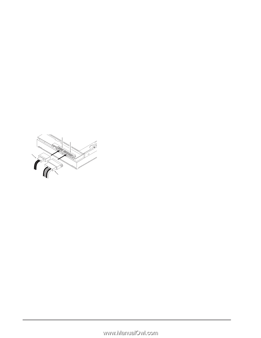
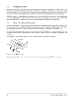
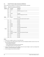
3.2 Configuring the drive Each drive on the Serial ATA interface connects point-to-point with the Serial ATA host adapter. There is no master/slave relationship because each drive is considered a master in a point-to-point relationship. If two drives are attached on one Serial ATA host adapter, the host operating system views the two devices as if they were both "masters" on two separate ports. Both drives behave as if they are Device 0 (master) devices. Serial ATA drives are designed for easy installation. If you connect the drive and receive a "drive not detected" error, your SATA equipped motherboard or host adapter may use a chipset that does not support SATA 3.0Gb speed autonegotiation. You will need to install a SATA host adapter that supports autonegotiation. 3.3 Serial ATA cables and connectors The Serial ATA interface cable consists of four conductors in two differential pairs, plus three ground connections. The cable size may be 30 to 26 AWG with a maximum length of one meter (39.37 inches). See Table 6 for connector pin definitions. Either end of the SATA signal cable can be attached to the drive or host. For direct backplane connection, the drive connectors are inserted directly into the host receptacle. The drive and the host receptacle incorporate features that enable the direct connection to be hot pluggable and blind mateable. For installations which require cables, you can connect the drive as illustrated in Figure 2. Signal connector Power connector Signal cable Power cable Figure 2. Attaching SATA cabling Each cable is keyed to ensure correct orientation. Pulsar drives support latching SATA connectors. 20 Pulsar Product Manual, Rev. A
-
 1
1 -
2
-
3
-
4
-
5
-
6
-
7
-
8
-
9
-
10
-
11
-
12
-
13
-
14
-
15
-
16
-
17
-
18
-
19
-
20
-
 21
21 -
 22
22 -
 23
23 -
 24
24 -
 25
25 -
 26
26 -
 27
27 -
 28
28 -
 29
29 -
 30
30 -
 31
31 -
32
-
33
-
34
-
35
-
36
-
37
-
38
-
39
-
40
-
41
-
42
-
43
-
44
-
45
-
46
-
47
-
48
-
49
-
50
 |
 |