Seagate ST800FM0053 Seagate 1200 SSD Product Manual - Page 75
Table 24, Micro SAS pin descriptions
 |
View all Seagate ST800FM0053 manuals
Add to My Manuals
Save this manual to your list of manuals |
Page 75 highlights
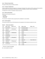
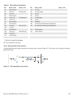
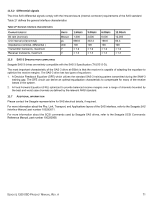
Table 24 Micro SAS pin descriptions PIN SIGNAL NAME SIGNAL TYPE S1 S2* S3* S4 S5* S6* S7 S8 S9* S10* S11 S12* S13* S14 Port A Ground +Port A_in -Port A_in Port A Ground -Port A_out +Port A_out Port A Ground Port B Ground +Port B_in -Port B_in Port B Ground -Port B_out +Port B_out Port B Ground Diff. input pair Diff output pair Diff. input pair Diff output pair PIN SIGNAL NAME P1* 3.3 Volts P2 3.3 Volts charge P3 Ground P4 Ground P5 5 Volts charge P6* 5 Volts P7* Reserved P8* NC (reserved for Manufacturing diagnostic) P9* NC (reserved for Manufacturing diagnostic) SIGNAL TYPE A1* Vendor specific A2* Vendor specific * - Short pin to support hot plugging NC - No connection in the drive. 11.4.6 SAS transmitters and receivers A typical SAS differential copper transmitter and receiver pair is shown in Figure 27. The receiver is AC coupling to eliminate ground shift noise. Figure 27. SAS transmitters and receivers SEAGATE 1200 SSD PRODUCT MANUAL, REV. A 69
-
 1
1 -
2
-
3
-
4
-
5
-
6
-
7
-
8
-
9
-
10
-
11
-
12
-
13
-
14
-
15
-
16
-
17
-
18
-
19
-
20
-
21
-
22
-
23
-
24
-
25
-
26
-
27
-
28
-
29
-
30
-
31
-
32
-
33
-
34
-
35
-
36
-
37
-
38
-
39
-
40
-
41
-
42
-
43
-
44
-
45
-
46
-
47
-
48
-
49
-
50
-
51
-
52
-
53
-
54
-
55
-
56
-
57
-
58
-
59
-
60
-
61
-
62
-
63
-
64
-
65
-
66
-
67
-
68
-
69
-
 70
70 -
 71
71 -
 72
72 -
 73
73 -
 74
74 -
 75
75 -
 76
76 -
 77
77 -
 78
78 -
 79
79 -
 80
80 -
81
-
82
 |
 |
