Seagate ST9500621SS Constellation.2 SATA Product Manual - Page 31
Configuring the drive, Serial ATA cables and connectors, Drive mounting
 |
View all Seagate ST9500621SS manuals
Add to My Manuals
Save this manual to your list of manuals |
Page 31 highlights
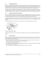
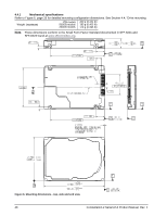
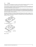
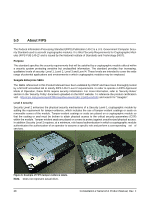
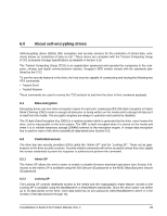
4.2 Configuring the drive Each drive on the Serial ATA interface connects point-to-point with the Serial ATA host adapter. There is no master/slave relationship because each drive is considered a master in a point-to-point relationship. If two drives are attached on one Serial ATA host adapter, the host operating system views the two devices as if they were both "masters" on two separate ports. Both drives behave as if they are Device 0 (master) devices. Serial ATA drives are designed for easy installation. It is usually not necessary to set any jumpers on the drive for proper operation; however, if you connect the drive and receive a "drive not detected" error, your SATAequipped motherboard or host adapter may use a chipset that does not support SATA speed autonegotiation. 4.3 Serial ATA cables and connectors The Serial ATA interface cable consists of four conductors in two differential pairs, plus three ground connections. The cable size may be 30 to 26 AWG with a maximum length of one meter (39.37in). See Table 5 for connector pin definitions. Either end of the SATA signal cable can be attached to the drive or host. For direct backplane connection, the drive connectors are inserted directly into the host receptacle. The drive and the host receptacle incorporate features that enable the direct connection to be hot pluggable and blind mateable. For installations which require cables, you can connect the drive as illustrated in Figure 5, page 25. Signal connector Power connector Signal cable Power cable Figure 5. Attaching SATA cabling Each cable is keyed to ensure correct orientation. Constellation.2 Serial ATA drives support latching SATA connectors. 4.4 Drive mounting You can mount the drive in any orientation using four screws in the side-mounting holes or four screws in the bottom-mounting holes. See Figure 6, page 26 for drive mounting dimensions. Follow these important mounting precautions when mounting the drive: • Allow a minimum clearance of 0.030 in (0.76 mm) around the entire perimeter of the drive for cooling as a guideline. Please refer to Section 4.5 for final cooling requirements. • Use only M3 x 0.5 metric mounting screws. • Four (4) threads (0.080 in) minimum screw engagement recommended. Also ensure maximum screw length does not bottom out in mounting holes. • Do not overtighten the mounting screws (maximum torque: 4.5 in-lb, ± 0.45 in-lb) Constellation.2 Serial ATA Product Manual, Rev. F 25
-
 1
1 -
2
-
3
-
4
-
5
-
6
-
7
-
8
-
9
-
10
-
11
-
12
-
13
-
14
-
15
-
16
-
17
-
18
-
19
-
20
-
21
-
22
-
23
-
24
-
25
-
 26
26 -
 27
27 -
 28
28 -
 29
29 -
 30
30 -
 31
31 -
 32
32 -
 33
33 -
 34
34 -
 35
35 -
 36
36 -
37
-
38
-
39
-
40
-
41
-
42
-
43
-
44
-
45
-
46
-
47
-
48
-
49
-
50
-
51
-
52
-
53
-
54
 |
 |
