Seagate ST9900805SS Savvio 10K.1 SAS Product Manual - Page 71
Transmitter signal characteristics, Table 27
 |
View all Seagate ST9900805SS manuals
Add to My Manuals
Save this manual to your list of manuals |
Page 71 highlights
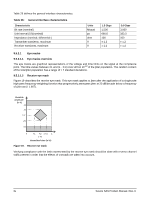
9.5.2.2 Transmitter signal characteristics Table 27 specifies the signal requirements at the transmitter end of a TxRx connection as measured into the zero-length test load. All specifications are based on differential measurements. The OOB sequence is performed at signal voltage levels corresponding to the lowest supported transfer rate. Table 27 specifies the signal characteristics. Table 27: Transmitter signal characteristics Signal characteristica Skewb Tx Off Voltagec Maximum rise/fall timed Minimum rise/fall timed Maximum transmitter output imbalancee OOB offset deltaf OOB common mode deltag Units ps mV(P-P) ps ps % mV mV 1.5 Gbps 20 < 50 273 67 10 ± 25 ± 50 3.0 Gbps 15 < 50 137 67 10 ± 25 ± 50 a All tests in this table shall be performed with zero-length test load shown in figure 23. b The skew measurement shall be made at the midpoint of the transition with a repeating 0101b pattern on the physical link. The same stable trigger, coherent to the data stream, shall be used for both the Tx+ and Tx- signals. Skew is defined as the time difference between the means of the midpoint crossing times of the Tx+ signal and the Tx- signal. c The transmitter off voltage is the maximum A.C. voltage measured at compliance points when the transmitter is unpowered or transmitting D.C. idle (e.g., during idle time of an OOB signal). d Rise/fall times are measured from 20 % to 80 % of the transition with a repeating 0101b pattern on the physical link. e The maximum difference between the V+ and V- A.C. RMS transmitter amplitudes measured on a CJTPAT test pattern (see 9.5.2.3.3) into the test load shown in figure 23, as a percentage of the average of the V+ and V- A.C. RMS amplitudes. f The maximum difference in the average differential voltage (D.C. offset) component between the burst times and the idle times of an OOB signal. g The maximum difference in the average of the common mode voltage between the burst times and the idle times of an OOB signal. Savvio SAS Product Manual, Rev. D 65
-
 1
1 -
2
-
3
-
4
-
5
-
6
-
7
-
8
-
9
-
10
-
11
-
12
-
13
-
14
-
15
-
16
-
17
-
18
-
19
-
20
-
21
-
22
-
23
-
24
-
25
-
26
-
27
-
28
-
29
-
30
-
31
-
32
-
33
-
34
-
35
-
36
-
37
-
38
-
39
-
40
-
41
-
42
-
43
-
44
-
45
-
46
-
47
-
48
-
49
-
50
-
51
-
52
-
53
-
54
-
55
-
56
-
57
-
58
-
59
-
60
-
61
-
62
-
63
-
64
-
65
-
 66
66 -
 67
67 -
 68
68 -
 69
69 -
 70
70 -
 71
71 -
 72
72 -
 73
73 -
 74
74 -
 75
75 -
 76
76 -
77
-
78
-
79
-
80
-
81
-
82
-
83
-
84
-
85
-
86
 |
 |
