Sharp AF-S125EX AF-R100EX , AF-R120EX Operation Manual - Page 6
WARNING, CAUTION, board or other hard filler.
 |
View all Sharp AF-S125EX manuals
Add to My Manuals
Save this manual to your list of manuals |
Page 6 highlights
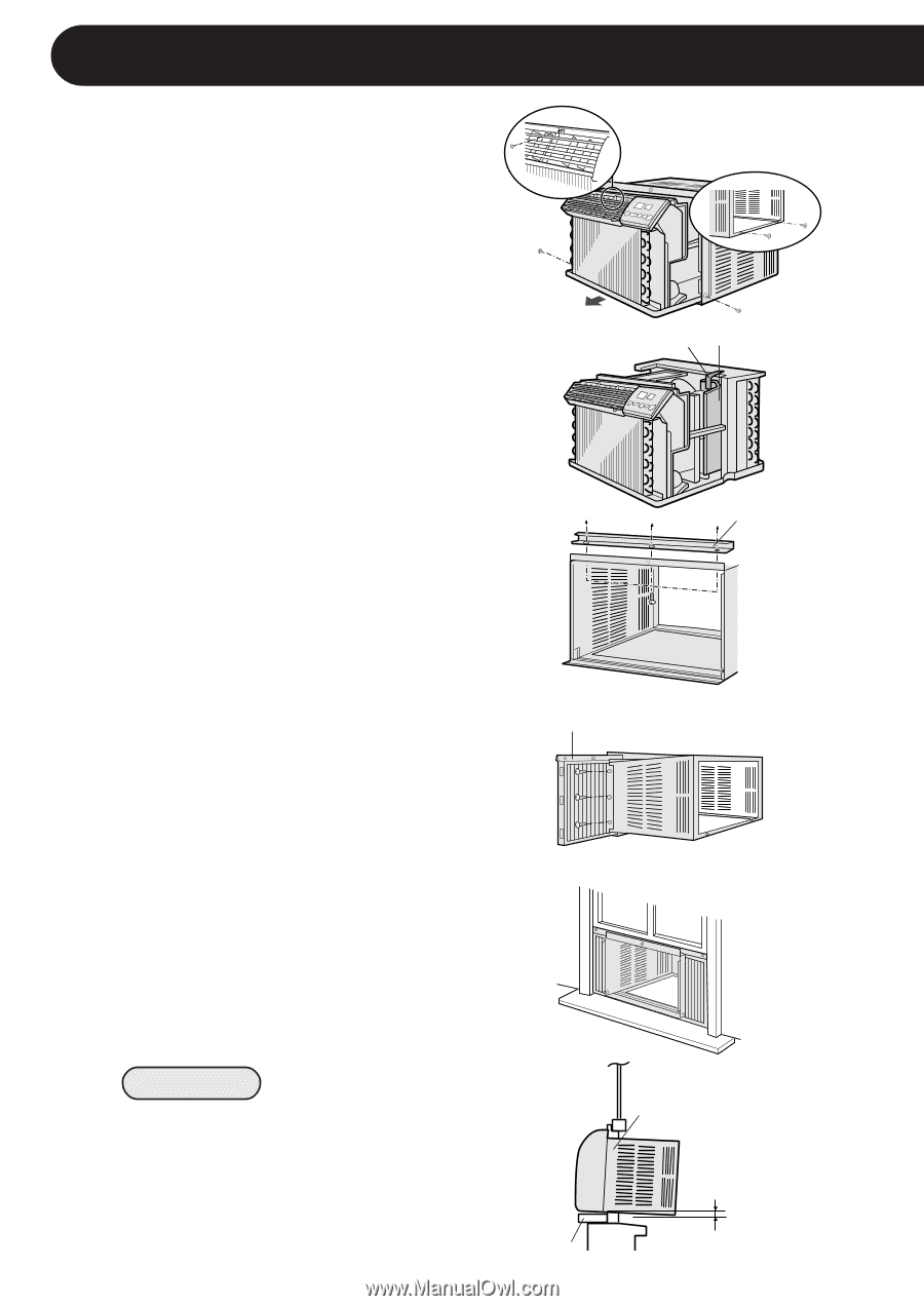
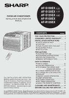
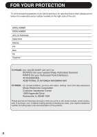
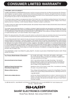
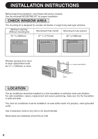
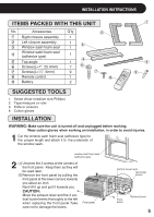
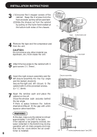
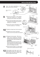
INSTALLATION INSTRUCTIONS 3 (1)Unscrew the 5 stopper screws of the cabinet. Keep the 3 screws from the front and side, as they will be used later. (2)Slide the chassis out from the cabinet by pulling on the hand hold located at the bottom both sides of the chassis. 4 Remove the tape and the compressor pad from the unit. CAUTION: Do not remove any other material (ex. styrofoam, etc.) from inside the unit. Tape Compressor pad Top angle 5 Attach the top angle to the cabinet with 3 gold screws (1/4", 6mm) . 6 Insert the right closure assembly and the left closure assembly into the top angle and the bottom channels. Secure the right and left closure to the cabinet with 6 of the provided screws. (L= 1/4", 6mm) 7 Open the window sash and place the cabinet on the sill. Close the window sash securely behind the top angle. If there is space between the bottom channel and the sill, fill the gap with a thin board or other hard filler. WARNING At this step, make sure the cabinet is inclined approximately 1 cm (3/8") to the back. If the cabinet is not properly inclined, the water collected in the bottom tray during operation will not drain properly and may flow into the room where the air conditioner is installed. 6 Closure assembly Cabinet sill incline backwards about 1cm (3/8")
-
 1
1 -
 2
2 -
 3
3 -
 4
4 -
 5
5 -
 6
6 -
 7
7 -
 8
8 -
 9
9 -
 10
10 -
 11
11 -
 12
12 -
13
-
14
-
15
-
16
-
17
-
18
-
19
-
20
 |
 |