Sharp AN-PHCM20 Installation Instructions - Page 5
Ceiling Bracket An-phcm20
 |
View all Sharp AN-PHCM20 manuals
Add to My Manuals
Save this manual to your list of manuals |
Page 5 highlights
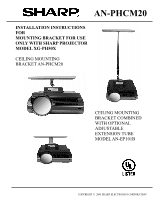
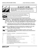
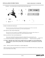
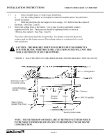
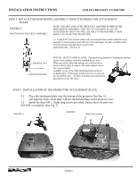
INSTALLATION INSTRUCTIONS CEILING BRACKET AN-PHCM20 FIGURE 3 ILLUSTRATION OF SINGLE BEAM CEILING BRACKET INSTALLATION Ceiling Beam Sheetrock or lath and plaster ceiling Washers 1/4 x 10 Lag Bolts Ceiling Mounting Bracket Cable access hole Security Bushing Velcro DO NOT RUN THE AC POWER CORD THROUGH THE CEILING PLATE AND TRIM COVER STEP 2. INSTALL THE CEILING MOUNT PLASTIC TRIM 2.1 The Access Hole (See Fig. 4) in the ceiling attachment plate is large enough to accommodate the molded connec- tors commonly used the with projector. 2.2 Audio, Video and other low voltage connections may be passed through the access hole in the ceiling plate and may also be passed through the plastic trim cover. There is a label (See Fig. 4) on the in- side of the plastic trim cover, adjacent to the center mounting bushing. 2.3 Select the contour appropriate for your application and cut out the opening along the line indicated on the label. Use a very sharp cutting tool. 2.4 Thread the cable through the plastic trim cover. Place the plastic trim cover in place over the ceiling plate and press the velcro tabs together. FIGURE 4 INSTALLATION OF PLASTIC TRIM ON THE CEILING BRACKET Cable Access Hole Security Bushing for use with Optional Security Cable Kit Model AN-CMCSS16 or AN-CMCSS46 Access Hole Template Label Press Velcro Tabs together to secure plastic trim cover in position PAGE 5
-
 1
1 -
 2
2 -
 3
3 -
 4
4 -
 5
5 -
 6
6 -
 7
7 -
 8
8 -
 9
9 -
 10
10 -
 11
11 -
12
-
13
 |
 |
