Sharp AN-PHCM20 Installation Instructions - Page 6
Detach The Positioning Assembly From The Projector Attachment
 |
View all Sharp AN-PHCM20 manuals
Add to My Manuals
Save this manual to your list of manuals |
Page 6 highlights
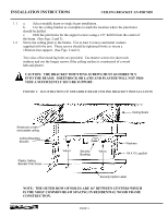
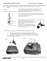
INSTALLATION INSTRUCTIONS CEILING BRACKET AN-PHCM20 STEP 3 DETACH THE POSITIONING ASSEMBLY FROM THE PROJECTOR ATTACHMENT PLATE. FIGURE 5 POSITIONING KNUCKLE ASSEMBLY NOTE: PLEASE LOOK OVER THE EXACT MANNER IN WHICH THE POSITIONING ASSEMBLY AND THE ATTACHMENT PLATE GO TOGETHER SO THAT YOU WILL BE ABLE TO REASSEMBLE THEM WHEN YOU HANG THE PROJECTOR. 3.1 Using 9/16" box wrench, remove the nut and split lock washer from the lower knuckle (vertical position) and slide the center and upper knuckle assembly apart from the bottom knuckle which is part of the attachment plate. (See Fig. 5) REMOVE NUT LOWER KNUCKLE SPECIAL NOTE TO INSTALLERS: The positioning knuckle is mounted to provide correct static balance when the standard lens is used. When any of the other lens options are used the lens is heavier and in order to improve the static balance, move the 3 piece knuckle assembly to one of the other mounting holes on the attachment plate. If the larger and heavier lens is selected, use the furthest hole. All other mounting and adjustment procedures remain the same. STEP 4 INSTALLATION OF THE PROJECTOR ATTACHMENT PLATE 4.1 Place the attachment plate over the bottom of the projector (See Fig. 6) and align the holes of the plate with the threaded fittings on the projector case. 4.2 Install the three M4 x 12mm long screws provided. Fasten these securely but DO NOT overtighten. (See Fig. 7) FIGURE 6. FIGURE 7. M4x12mm screws PAGE 6
-
 1
1 -
 2
2 -
 3
3 -
 4
4 -
 5
5 -
 6
6 -
 7
7 -
 8
8 -
 9
9 -
 10
10 -
 11
11 -
 12
12 -
13
 |
 |
