Sharp DV-SL90UA Service Manual
Sharp DV-SL90UA Manual
 |
View all Sharp DV-SL90UA manuals
Add to My Manuals
Save this manual to your list of manuals |
Sharp DV-SL90UA manual content summary:
- Sharp DV-SL90UA | Service Manual - Page 1
SERVICE MANUAL DV-SL90UA SERVICE MANUAL S74X3DV-SL90U DVD VIDEO PLAYER The region number for this DVD player is NOTES FOR SERVICING 1-4-1 OPERATING CONTROLS AND FUNCTIONS 1-5-1 CABINET DISASSEMBLY INSTRUCTIONS 1-6-1 FIRMWARE RENEWAL MODE (FIRMWARE VERSION UP 1-7-1 TROUBLESHOOTING ...1-8-1 BLOCK - Sharp DV-SL90UA | Service Manual - Page 2
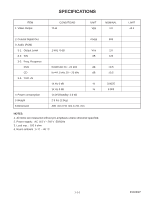
SPECIFICATIONS ITEM 1 Video Output CONDITIONS 75 Ω UNIT Vpp NOMINAL 1.0 2 Coaxial Digital Out 3 Audio (PCM) 3-1. Output Level 3-2. S/N 3-3. Freq. Response DVD CD 3-4. THD +N 4 Power consumption 5 Weight 6 Dimension mVpp 1 kHz 0 dB Vrm dB fs=48 kHz 20 ~ 22 kHz dB fs=44.1 kHz 20 ~ 20 kHz - Sharp DV-SL90UA | Service Manual - Page 3
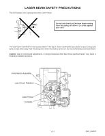
LASER BEAM SAFETY PRECAUTIONS This DVD player uses a pickup that emits a laser beam. Do not look directly at the laser beam coming from the pickup or allow it to strike against your skin. The laser beam is emitted from the location shown in the figure. When checking the laser diode, be sure to keep - Sharp DV-SL90UA | Service Manual - Page 4
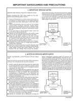
to the owner. SSVM AC SCALE 1.5k ohms. 10W TO EXPOSED METAL PARTS 0.15 F TEST PROBE CONNECT TO KNOWN EARTH GROUNG 1. NOTES DE SERVICE IMPORTANTES AVANT DE RENDRE LE REPRODUCTOR DE VíDEO DVD Avant de rendre le reproductor de vídeo DVD à l'utilisateur, effectuer les vérifications de sécurit - Sharp DV-SL90UA | Service Manual - Page 5
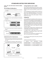
to obtain lead-free wire solder or soldering bit, contact our service station or service branch in your area. Soldering As the melting point of blackened during use, file it with steel wool or fine sandpaper. Instructions for Connectors 1. When you connect or disconnect the FFC (Flexible Foil Connector - Sharp DV-SL90UA | Service Manual - Page 6
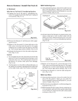
How to Remove / Install Flat Pack-IC 1. Removal With Hot-Air Flat Pack-IC Desoldering Machine: (1) Prepare the hot-air flat pack-IC desoldering ma- chine, then apply hot air to the Flat Pack-IC (about 5 to 6 seconds). (Fig. S-1-1) With Soldering Iron: (1) Using desoldering braid, remove the solder - Sharp DV-SL90UA | Service Manual - Page 7
(4) Bottom of the flat pack-IC is fixed with glue to the CBA; when removing entire flat pack-IC, first apply soldering iron to center of the flat pack-IC and heat up. Then remove (glue will be melted). (Fig. S-1-6) (5) Release the flat pack-IC from the CBA using tweezers. (Fig. S-1-6) Note: When - Sharp DV-SL90UA | Service Manual - Page 8
Instructions for Handling Semi-conductors Electrostatic breakdown of the semi-conductors may occur due to a potential difference caused by electrostatic charge during unpacking or repair work. 1. - Sharp DV-SL90UA | Service Manual - Page 9
OPERATING CONTROLS AND FUNCTIONS FRONT PANEL REAR VIEW 10 1112 13 14 15 16 1. POWER to switch the player to ON or OFF 2. SKIP / REV goes to previous chapter or track during playback; press and hold for 1.5 seconds for a reverse search 3. PLAY to start or resume disc playback 4. SKIP / FWD goes - Sharp DV-SL90UA | Service Manual - Page 10
CABINET DISASSEMBLY INSTRUCTIONS NOTE: CBA AND PWB MEANS PRINTED WIRING BOARD. 1. Disassembly Flowchart This flowchart indicates the disassembly steps to gain access to item(s) to be serviced. When reassembling, follow the steps in reverse order. Bend, route, and dress the cables as they were - Sharp DV-SL90UA | Service Manual - Page 11
[1] Top Case (S-1) (L-1) (L-3) (L-1) Fig. 1 (L-2) [2] Front Assembly Fig. 2 (S-2) [3] Reinforce Plate CN201 CN301 (S-3B) (S-3A) CN601 CN401 A [4] DVD Main CBA Unit Solder Short lands OR Short lands Short the three short lands by soldering. (Either of two places.) Solder FPC Cable - Sharp DV-SL90UA | Service Manual - Page 12
[7] Function CBA (S-5) [6] AV CBA CN2001 (S-6) (L-5) Fig. 6 HOW TO EJECT MANUALLY (Method 1) 1 Remove the Top Case. 2 Remove the Reinforce Plate. 3 Rotate the roulette in the direction of the arrow as shown below. View for A Rotate this roulette in the direction of the arrow A 1-6-3 E592BDC - Sharp DV-SL90UA | Service Manual - Page 13
HOW TO EJECT MANUALLY (Method 2) 1 Turn the unit over. 2 Insert the shaft less than a diameter of 3 mm (e.g. screwdriver) straightly into the opening as shown. 3 Turn the shaft along with - Sharp DV-SL90UA | Service Manual - Page 14
FIRMWARE RENEWAL MODE (FIRMWARE VERSION UP) FIRMWARE is built-in program to operate DVD player. To get rid of error when playing new software (disc) in the market, FIRMWARE version is updated. Perform the following to update the FIRMWARE version. NOTES: a. This unit can not read data which is - Sharp DV-SL90UA | Service Manual - Page 15
"*******" differ depending on the models. MODEL : ******* Version : *.** Region : * EEPROM CLEAR : CLEAR EXIT: POWER Fig. g 10.Press [CLEAR] button on the remote control unit. Fig. h appears on the screen. "*******" differ depending on the models. MODEL : ******* Version : *.** Region : * EEPROM - Sharp DV-SL90UA | Service Manual - Page 16
Table of Contents for the Troubleshooting Flow Charts Flow Chart No. Description 1 The power cannot be turned on. 2 The fuse blows out. 3 When the output voltage fluctuates. 4 When buzz sound can - Sharp DV-SL90UA | Service Manual - Page 17
if defective. FLOW CHART NO.4 When buzz sound can be heard in the vicinity of power circuit. Check IC1001, IC1006, D1048 and their periphery, and service it if defective. Check if there is any short-circuit on the rectifying diode and the circuit in each rectifying circuit of the secondary side - Sharp DV-SL90UA | Service Manual - Page 18
not outputted. (EV+11V is outputted normally.) Is the "H" signal inputted into the base of Q1004? No Yes Replace Q1004. Check R1068 and D1046, and service it if defective. FLOW CHART NO.8 P-ON+3.3V is not outputted. (P-ON+10 V is outputted normally.) Is 3.3V voltage supplied to the collector of - Sharp DV-SL90UA | Service Manual - Page 19
, SW2104-2108) correctly or replace the poor switch. Check the switches (SW2101, SW2104-2108) and their periphery, and service it if detective. Check EV+5V line and service it if defective. Replace the infrared remote control receiver (RM2001). Or replace the remote control unit. Check the line - Sharp DV-SL90UA | Service Manual - Page 20
FLOW CHART NO.14 The disc tray cannot be opened and closed. (It can be done using the remote control unit.) No Is the normal control voltage inputted to Pin(4) of IC2001? Refer to "FLOW CHART NO.12" Yes Refer to "FLOW CHART NO.15" - Sharp DV-SL90UA | Service Manual - Page 21
DVD Main CBA or DVD Mecha. Check the line between each pin of CN1601 and each pin of IC1402, IC1403 on the AV CBA, and service it if detective. CN1601 CN1601 CN1601 CN1601 CN1601 8PIN → IC1402 6PIN → IC1402 4PIN → IC1402 3PIN → IC1403 10PIN → IC1403 3PIN Y 6PIN Cb/Pb 8PIN Cr/Pr - Sharp DV-SL90UA | Service Manual - Page 22
)? Replace the DVD Main CBA or DVD Mecha. Check each line between each pin of CN1601 and each pin of IC1201 on AV CBA, and service it if detective. CN1601 14PIN → IC1201 2PIN AUDIO-L CN1601 16PIN → IC1201 6PIN AUDIO-R Replace the DVD Main CBA or DVD Mecha. Replace IC1201. Check the - Sharp DV-SL90UA | Service Manual - Page 23
BLOCK DIAGRAMS System Control / Servo Block Diagram NOTE: CBA AND PWB MEANS PRINTED WIRING BOARD. 1-9-1 TO VIDEO/ AUDIO BLOCK DIAGRAM PCM-SCLK A-MUTE ADAC-MD ADAC-MC ADAC-ML TO DIGITAL SIGNAL PROCESS BLOCK DIAGRAM FS(+) FS(-) TS(+) TS(-) +3.3V IC461 +3.3V IC462 2 RESET 1 1 RESET 3 IC301 ( - Sharp DV-SL90UA | Service Manual - Page 24
VIDEO/AUDIO) SIGNAL VIDEO SIGNAL DATA(AUDIO) SIGNAL *Note: IC103 is not supplied separatery. Be sure to replace with the DVD Main CBA unit when servicing IC103. IC503 (SDRAM) SDRAM IC101 (MICRO CONTROLLER) ~~ 22 26 SDRAM ADDRESS(0-11) 217 SDRAM ADDRESS(0-11) ~ 29 238 35 EXTERNAL MEMORY - Sharp DV-SL90UA | Service Manual - Page 25
Video / Audio Block Diagram NOTE: CBA AND PWB MEANS PRINTED WIRING BOARD. IC1403 (VIDEO DRIVER) 4dB 3 AMP TO DIGITAL SIGNAL PROCESS BLOCK DIAGRAM VIDEO-Y(I) VIDEO-C VIDEO-Y VIDEO-Cb/Pb VIDEO-Cr/Pr CN601 CN1601 3 VIDEO-Y(I) 3 WF1 10 VIDEO-C 10 WF5 8 VIDEO-Y 8 6 VIDEO-Cb/Pb 6 WF3 4 - Sharp DV-SL90UA | Service Manual - Page 26
Power Supply Block Diagram CAUTION ! Fixed voltage ( or Auto voltage selectable ) power supply circuit is used in this unit. If Main Fuse (F1001) is blown, check to see that all components in the power supply circuit are not defective before you connect the AC plug to the AC power supply. Otherwise - Sharp DV-SL90UA | Service Manual - Page 27
identified by the mark " # " in the schematic diagram and the parts list. Before replacing any of these components, read the parts list in this manual carefully. The use of substitute replacement parts that do not have the same safety characteristics as specified in the parts list may create shock - Sharp DV-SL90UA | Service Manual - Page 28
of repaired units, use only original replacement parts which are listed with their part numbers in the parts list section of the service manual. 4. Voltage indications for PLAY and STOP mode on the schematics are as shown below: 1 2 (Unit: Volt) 5.0 3 5.0 (2.5) PLAY mode STOP mode The same - Sharp DV-SL90UA | Service Manual - Page 29
DVD Main 1/3 Schematic Diagram NOTE: CBA AND PWB MEANS PRINTED WIRING BOARD. 1-10-3 1-10-4 E592BSCD1 - Sharp DV-SL90UA | Service Manual - Page 30
DVD Main 2/3 Schematic Diagram NOTE: CBA AND PWB MEANS PRINTED WIRING BOARD. 1-10-5 1-10-6 E592BSCD2 - Sharp DV-SL90UA | Service Manual - Page 31
IC101 VOLTAGE CHART PIN.NO PLAY STOP PIN.NO PLAY 1 ~ ~ 33 ~ 2 ~ ~ 34 3.4 3 0 0 35 0 4 ~ ~ 36 ~ 5 ~ ~ 37 ~ 6 3.4 3.4 38 0.4 7 ~ ~ 39 ~ 8 ~ ~ 40 ~ 9 0 0 41 ~ 10 ~ ~ 42 ~ 11 ~ ~ 43 ~ 12 3.4 3.4 44 1.3 13 ~ ~ 45 ~ 14 ~ ~ 46 ~ 15 ~ - Sharp DV-SL90UA | Service Manual - Page 32
DVD Main 3/3 Schematic Diagram * Note: IC103 is not supplied separately. Be sure to replace with the DVD Main CBA unit when servicing IC103. NOTE: CBA AND PWB MEANS PRINTED WIRING BOARD. 1-10-9 1-10-10 E592BSCD3 - Sharp DV-SL90UA | Service Manual - Page 33
AV 1/3 Schematic Diagram CAUTION ! Fixed voltage ( or Auto voltage selectable ) power supply circuit is used in this unit. If Main Fuse (F1001) is blown, check to see that all components in the power supply circuit are not defective before you connect the AC plug to the AC power supply. Otherwise - Sharp DV-SL90UA | Service Manual - Page 34
AV 2/3 Schematic Diagram NOTE: CBA AND PWB MEANS PRINTED WIRING BOARD. 1-10-13 1-10-14 E592BSCAV2 - Sharp DV-SL90UA | Service Manual - Page 35
AV 3/3 & Function Schematic Diagram 7G 6G 5G 4G 3G 2G 1G VCR REPEAT TITLE GROUP AB ALL f i i REC SACD CHP TRK PSCAN a c b DVD A d PM f g e HD VCD NOTE: CBA AND PWB MEANS PRINTED WIRING BOARD. FL2001 MATRIX CHART 7G 6G 5G 4G a a a a b REPEAT b b b cA c c c dB d d d e - Sharp DV-SL90UA | Service Manual - Page 36
DVD MAIN CBA Top View WF1 ~ WF7 CN601 WF9 ~ WF12 CN401 1-10-17 NOTE: CBA AND PWB MEANS PRINTED WIRING BOARD. NOTE : Either BE5900G04012,BE5900G04014 is used for the DVD MAIN CBA in this S/M. WF17 WF18 CN201 1-10-18 BE5900G04012 - Sharp DV-SL90UA | Service Manual - Page 37
DVD MAIN CBA Bottom View NOTE: CBA AND PWB MEANS PRINTED WIRING BOARD. NOTE : Either BE5900G04012,BE5900G04014 is used for the DVD MAIN CBA in this S/M. 1-10-19 1-10-20 BE5900G04012 - Sharp DV-SL90UA | Service Manual - Page 38
DVD MAIN CBA Top View WF1 ~ WF7 CN601 WF9 ~ WF12 CN401 1-10-21 NOTE: CBA AND PWB MEANS PRINTED WIRING BOARD. NOTE : Either BE5900G04012,BE5900G04014 is used for the DVD MAIN CBA in this S/M. WF17 WF18 CN201 1-10-22 BE5900G04014 - Sharp DV-SL90UA | Service Manual - Page 39
DVD MAIN CBA Bottom View NOTE: CBA AND PWB MEANS PRINTED WIRING BOARD. NOTE : Either BE5900G04012,BE5900G04014 is used for the DVD MAIN CBA in this S/M. 1-10-23 1-10-24 BE5900G04014 - Sharp DV-SL90UA | Service Manual - Page 40
AV CBA Top View CAUTION ! Fixed voltage ( or Auto voltage selectable ) power supply circuit is used in this unit. If Main Fuse (F1001) is blown, check to see that all components in the power supply circuit are not defective before you connect the AC plug to the AC power supply. Otherwise it may - Sharp DV-SL90UA | Service Manual - Page 41
AV CBA Bottom View CAUTION ! Fixed voltage ( or Auto voltage selectable ) power supply circuit is used in this unit. If Main Fuse (F1001) is blown, check to see that all components in the power supply circuit are not defective before you connect the AC plug to the AC power supply. Otherwise it may - Sharp DV-SL90UA | Service Manual - Page 42
FUNCTION CBA Top View FUNCTION CBA Bottom View WF13 ~ WF16 CN2101 1-10-29 NOTE: CBA AND PWB MEANS PRINTED WIRING BOARD. 1-10-30 BE5942F01011B - Sharp DV-SL90UA | Service Manual - Page 43
PIN DESCRIPTION FOR DVD MAIN CN201 PIN DESCRIPTION Pin No. Signal Name 1 TS(+) 2 FS(+) 3 FS(-) 4 TS(-) 5 GND(CD-PD) 6 GND(DVD-PD) 7 PD-MONI 8 DVD-LD 9 GND(LD) 10 CD-LD 11 GND 12 F 13 VREF 14 E 15 B 16 C 17 A 18 D 19 CD/DVD 20 P-ON+5V CN301 PIN DESCRIPTION PIN NO. Signal Name 3 SP(+) 4 SP(-) 5 TRAY- - Sharp DV-SL90UA | Service Manual - Page 44
DVD MAIN CN201 Pin Voltage No. / WF No. 1 WF17 2 WF18 3 WF18 4 WF17 5 0 6 0 7 0.2 8 2.7 9 0 10 0.1 11 0 12 2.2 13 2.2 14 2.2 15 2.2 16 2.2 17 2.2 18 2.2 19 0.1 20 5.0 CN301 Pin No. 3 4 5 6 7 8 Voltage / WF No. 3.9 3.9 3.4 0 1.7 1.7 WAVEFORMS & VOLTAGE - Sharp DV-SL90UA | Service Manual - Page 45
WF1 Pin 3 of CN1601(AV) Pin 3 of CN601(DVD MAIN) NOTE: Input CD: 1kHz PLAY (WF6~WF7) DVD: POWER ON (STOP) MODE (WF1~WF5,WF8~WF18) WF5 Pin 10 of CN1601(AV) WF9 Pin 18 of CN1001(AV) Pin 10 of CN601(DVD MAIN) Pin 18 of CN401(DVD MAIN) VIDEO-Y(I) 0.2V 20µs WF2 Pin 4 of CN1601(AV) Pin 4 of CN601 - Sharp DV-SL90UA | Service Manual - Page 46
NOTE: Input CD: 1kHz PLAY (WF6~WF7) DVD: POWER ON (STOP) MODE (WF1~WF5,WF8~WF18) WF13 Pin 3 of CN2001(AV) Pin 3 of CN2101(FUNCTION) WF17 Pin 1, 4 of CN201(DVD MAIN) KEY-2 2V 2ms TS(+/-) 1V 5ms WF14 Pin 4 of CN2001(AV) Pin 4 of CN2101(FUNCTION) WF18 Pin 2,3 of CN201(DVD MAIN) KEY-3 2V 2ms - Sharp DV-SL90UA | Service Manual - Page 47
WIRING DIAGRAM FUNCTION CBA (9HS1VSA10751B) CN2101 is soldered directly to the PCB. CN2101 1 2 3 4 5 6 NOTE: CBA AND PWB MEANS PRINTED WIRING BOARD. CN2001 1 K2 2 K1 3 KEY-2 4 KEY-3 5 KEY-1 6 KEY-4 CN1601 (CN1601 is soldered directly to the PCB.) AC CORD AV CBA (9HS1VSA10751A) DIGITAL AUDIO - Sharp DV-SL90UA | Service Manual - Page 48
SYSTEM CONTROL TIMING CHARTS Tray Close ~ Play / Play ~ Tray Open Tray IN (TL221) 3.3V 0V Tray Close Sled Drive (TP303) 1.65V 0V Disc Drive (TP301) 1.65V 0V Focus Drive (TP304) 1.65V 0V Tracking Drive 1.65V (TP302) 0V Disc Rotation Play Disc Tray Stop Open 1-13-1 E5945TI - Sharp DV-SL90UA | Service Manual - Page 49
IC PIN FUNCTION DESCRIPTIONS IC1001 (PHOTOCOUPLER) Pin Signal No. Name Function 1 ANODE Anode 2 CATHODE Cathode 3 EMITTER Emitter 4 COLLECTOR Collector IC1002 (REGULATOR) Pin Signal No. Name 1 VIN 2 VC 3 VOUT 4 VREF 5 GND Function DC Input ON/OFF Control DC Output Output - Sharp DV-SL90UA | Service Manual - Page 50
IC1403(VIDEO DRIVER) Pin Signal No. Name 1 C IN 2 BIAS 3 Y IN 4 VCC 5 Y OUT 6 CVBS OUT 7 C OUT 8 GND Function Chrominance Signal Input BIAS Luminance Signal(Interlace) Input VCC Luminance Signal Output Composite Video Signal Output Chrominance Signal Output GND IC2001 (FRONT PANEL - Sharp DV-SL90UA | Service Manual - Page 51
LEAD IDENTIFICATIONS KTC3203(Y) E C B KTA1266(Y) KRA110M KTA1267(Y) KTC3199(GR,Y) PQ070XZ5MZP 3 12345 1: Vin 2: Vc 3: Vo 4: Vadj 5: GND E C B MM1636XWRE 8 5 KIA4558P 8 5 PT6313-S-TP 28 15 KIA431-AT 1 4 1 4 1 14 MM1637XVBE 16 9 1 8 2SK3566 G D S LTV-817B-F A C K A R K - Sharp DV-SL90UA | Service Manual - Page 52
EXPLODED VIEWS NOTE: CBA AND PWB MEANS PRINTED WIRING BOARD. Cabinet See Electrical Parts List for parts with this mark. Some Ref. Numbers are not in sequence. 2L011 2L081 2B5 2L081 2L011 2L011 A2 2L021 2L021 2L021 Function CBA A16 2L021 1B1 2L105 DVD Main CBA Unit 2L105 2L031 JK1401 - Sharp DV-SL90UA | Service Manual - Page 53
Packing X10 X1 X5 X2 RIGHT REAR S2 S2 S1 1-16-2 X4 S4 Unit A30 A22 E592BEX - Sharp DV-SL90UA | Service Manual - Page 54
characteristics important to safety. Before replacing any of these components, read carefully the product safety notice in this service manual. Don't degrade the safety of the product through improper servicing. Ref. No. A1X A2 A13 A15 A16 A21# A22 A30 1B1 2B5 2L011 2L021 2L031 2L041 2L081 2L105 - Sharp DV-SL90UA | Service Manual - Page 55
to safety. Before replacing any of these components, read carefully the product safety notice in this service manual. Don't degrade the safety of the product through improper servicing. NOTES: 1. Parts that not assigned part numbers are not available. 2. IC103 is not supplied separately. Be - Sharp DV-SL90UA | Service Manual - Page 56
Ref. No. C210 C211 C212 C215 C217 C218 C219 C220 C221 C222 C223 C224 C225 C226 C227 C228 C229 C230 C231 C232 C233 C234 C237 C238 C239 C240 C241 C250 C253 C255 C257 C259 C263 C280 C281 C284 C288 C289 C301 C302 C303 C305 C308 C310 C311 C313 C314 C315 C316 C317 C318 C324 C325 C326 C327 C328 C329 C402 - Sharp DV-SL90UA | Service Manual - Page 57
Ref. No. C424 C425 C426 C471 C473 C501 C502 C503 C504 C505 C506 C507 C508 C509 C510 C511 C512 C514 C561 C601 C602 C605 C606 C608 C609 C610 C611 C616 C619 C620 C621 C622 C624 C658 C901 C902 C904 C905 C910 C913 C914 C915 C916 C917 C918 C919 CONNECTORS CN201 CN301 CN401 CN601 DIODE D204 ICs IC101 IC103 - Sharp DV-SL90UA | Service Manual - Page 58
Ref. No. L403 L501 L611 L612 L613 L614 L617 L618 TRANSISTORS Q251 Q252 Q253 Q254 RESISTORS R101 R102 R106 R107 R108 R109 R110 R112 R113 R114 R116 R120 R121 R122 R124 R128 R131 R133 R191 R192 R203 R213 R214 R225 R226 R227 R228 R231 R232 R233 R234 R241 R242 R251 R252 R255 R258 R261 R262 R265 R268 R270 - Sharp DV-SL90UA | Service Manual - Page 59
Ref. No. R286 R298 R299 R301 R302 R303 R305 R306 R307 R308 R313 R315 R316 R317 R318 R319 R320 R321 R322 R325 R335 R402 R403 R404 R405 R406 R407 R413 R415 R417 R421 R422 R423 R471 R474 R509 R510 R565 R567 R570 R601 R607 R610 MISCELLANEOUS X101 CHIP RES.(1005) 1/16W J 2.2k Ω CHIP RES.(1005) 1/16W J - Sharp DV-SL90UA | Service Manual - Page 60
Ref. No. C1014 C1017 C1018 C1021 C1022 C1029 C1032 C1033 C1034 C1035 C1036 C1037 C1038 C1039 C1047 C1048 C1049 C1201 C1202 C1205 C1206 C1207 C1208 C1221 C1222 C1223 C1224 C1245 C1246 C1247 C1249 C1250 C1351 C1352 C1354 C1355 C1361 C1362 C1394 C1395 C1402 C1403 C1422 C1423 C1441 C1442 C1443 C1461 - Sharp DV-SL90UA | Service Manual - Page 61
Ref. No. CN1601 CN2001 DIODES D1001 D1002 D1003 D1004 D1005 D1006 D1008 D1011 D1012 D1016 D1017 D1018 D1022 D1024 D1025 D1030 D1046 D1047 D1048 D1051 D1053 D1054 D1055 D1058 D1059 D1070 D1073 D1301 D2041 D2042 D2043 D2044 ICs IC1001# IC1002 IC1006 IC1201 IC1204 IC1402 IC1403 IC2001 COILS L1001# - Sharp DV-SL90UA | Service Manual - Page 62
Ref. No. Q1008 Q1011 Q1015 Q1016 Q1201 Q1202 Q1204 Q1351 Q1352 RESISTORS R1002 R1004 R1005 R1006 R1008 R1010 R1011 R1013 R1014 R1015 R1016 R1019 R1020 R1021 R1022 R1023 R1025 R1029 R1032 R1034 R1035 R1036 R1037 R1038 R1039 R1043 R1044 R1059 R1067 R1068 R1069 R1072 R1073 R1074 R1075 R1076 R1077 R1078 - Sharp DV-SL90UA | Service Manual - Page 63
Ref. No. R1223 R1224 R1225 R1226 R1227 R1228 R1236 R1238 R1240 R1245 R1351 R1352 R1353 R1354 R1355 R1356 R1366 R1392 R1396 R1397 R1402 R1403 R1421 R1422 R1441 R1442 R1443 R1461 R1462 R1481 R1482 R1614 R2001 R2002 R2012 R2013 R2014 R2015 R2016 R2031 R2032 R2033 R2041 R2042 R2043 R2044 R2045 - Sharp DV-SL90UA | Service Manual - Page 64
FUNCTION CBA Ref. No. CONNECTOR CN2101 RESISTORS R2101 R2102 R2103 R2104 R2105 R2106 SWITCHES SW2101 SW2104 SW2105 SW2106 SW2107 SW2108 FUNCTION CBA Consists of the following 6P FFC AV PCB TO SW PCB CHIP RES.(1608) 1/10W 0 Ω CHIP RES.(1608) 1/10W 0 Ω CHIP RES.(1608) 1/10W 0 Ω CHIP RES.(1608) 1/10W - Sharp DV-SL90UA | Service Manual - Page 65
DV-SL90UA COPYRIGHT © 2004 BY SHARP CORPORATION ALL RIGHTS RESERVED. No part of this publication may be reproduced, stored in a retrieval system, or transmitted in any form or by any means, electronic, mechanical, photocopying, recording, or otherwise, without prior written permission of the
-
 1
1 -
 2
2 -
 3
3 -
 4
4 -
 5
5 -
 6
6 -
 7
7 -
8
-
9
-
10
-
11
-
12
-
13
-
14
-
15
-
16
-
17
-
18
-
19
-
20
-
21
-
22
-
23
-
24
-
25
-
26
-
27
-
28
-
29
-
30
-
31
-
32
-
33
-
34
-
35
-
36
-
37
-
38
-
39
-
40
-
41
-
42
-
43
-
44
-
45
-
46
-
47
-
48
-
49
-
50
-
51
-
52
-
53
-
54
-
55
-
56
-
57
-
58
-
59
-
60
-
61
-
62
-
63
-
64
-
65
 |
 |
DV-SL90UA
S74X3DV-SL90U
SERVICE MANUAL
In the interests of user-safety (Required by safety
regulations in some countries) the set should be
restored to its original condition and only parts
identical to those specified be used.
MODEL
SERVICE MANUAL
DVD VIDEO PLAYER
MODEL
DV-SL90UA
DVD VIDEO PLAYER
This document has been published to be used for
after sales service only.
The contents are subject to change without notice.
SHARP CORPORATION
DV-SL90UA
Page
SPECIFICATIONS
.............................................................................................................................
1-1-1
LASER BEAM SAFETY PRECAUTIONS
..........................................................................................
1-2-1
IMPORTANT SAFEGUARDS AND PRECAUTIONS
.........................................................................
1-3-1
STANDARD NOTES FOR SERVICING
.............................................................................................
1-4-1
OPERATING CONTROLS AND FUNCTIONS
..................................................................................
1-5-1
CABINET DISASSEMBLY INSTRUCTIONS
.....................................................................................
1-6-1
FIRMWARE RENEWAL MODE (FIRMWARE VERSION UP)
...........................................................
1-7-1
TROUBLESHOOTING
.......................................................................................................................
1-8-1
BLOCK DIAGRAMS
...........................................................................................................................
1-9-1
SCHEMATIC DIAGRAMS/ CBA’S AND TEST POINTS
..................................................................
1-10-1
WAVEFORMS & VOLTAGE CHART
...............................................................................................
1-11-1
WIRING DIAGRAM
..........................................................................................................................
1-12-1
SYSTEM CONTROL TIMING CHARTS
..........................................................................................
1-13-1
IC PIN FUNCTION DESCRIPTIONS
...............................................................................................
1-14-1
LEAD IDENTIFICATIONS
................................................................................................................
1-15-1
EXPLODED VIEWS
.........................................................................................................................
1-16-1
MECHANICAL PARTS LIST
............................................................................................................
1-17-1
ELECTRICAL PARTS LIST
.............................................................................................................
1-18-1
CONTENTS
The region number for this DVD player is 4.
4