Sharp DV-SL90UA Service Manual - Page 10
CABINET DISASSEMBLY INSTRUCTIONS, Disassembly Flowchart, About tightening screws, Disassembly Method
 |
View all Sharp DV-SL90UA manuals
Add to My Manuals
Save this manual to your list of manuals |
Page 10 highlights
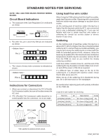
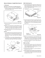
CABINET DISASSEMBLY INSTRUCTIONS NOTE: CBA AND PWB MEANS PRINTED WIRING BOARD. 1. Disassembly Flowchart This flowchart indicates the disassembly steps to gain access to item(s) to be serviced. When reassembling, follow the steps in reverse order. Bend, route, and dress the cables as they were originally. [1] Top Case [2] Front Assembly [3] Reinforce Plate [4] DVD Main CBA Unit [5] DVD Mecha [6] AV CBA [7] Function CBA 2. Disassembly Method ID/ LOC. PART No. [1] Top Case [2] Front Assembly [3] Reinforce Plate [4] DVD Main CBA Unit [5] DVD Mecha [6] AV CBA [7] Function CBA ↑ ↑ 1 2 REMOVAL Fig. REMOVE/ *UNHOOK/UNLOCK/ No. RELEASE/UNPLUG/ DESOLDER 1 3(S-1) 2 *4(L-1), *3(L-2), *3(L-3), 3 3(S-2) Note 1 1-1 1-2 - 4 (S-3A), (S-3B), 2 *CN201, *CN301, 2-1 *CN401, *CN601 2-2 3 5 4(S-4) 6 (S-5), 5(S-6), *2(L-5) - 6 *CN2001 - ↑ ↑ ↑ 3 4 5 1 : Identification (location) No. of parts in the figures 2 : Name of the part 3 : Figure Number for reference 4 : Identification of parts to be removed, unhooked, unlocked, released, unplugged, unclamped, or desoldered. P=Spring, L=Locking Tab, S=Screw, CN=Connector, *=Unhook, Unlock, Release, Unplug, or Desolder e.g. 5(S-1) = five Screws (S-1), 2(L-2) = two Locking Tabs (L-2) 5 : Refer to "Reference Notes." About tightening screws When tightening screws, tighten them with the following torque. Screws (S-1), (S-2), (S-3A), (S-4), (S-5), (S-6) (S-3B) Torque 0.45 ± 0.05 N•m 0.38 ± 0.04 N•m Reference Notes CAUTION 1: Locking Tabs (L-1), (L-2) and (L-3) are fragile. Be careful not to break them. 1-1. Release four Locking Tabs (L-1). Then, release three Locking Tabs (L-2). 1-2. Release three Locking Tabs (L-3). Then remove the Front Assembly. CAUTION 2: Electrostatic breakdown of the laser diode in the optical system block may occur as a potential difference caused by electrostatic charge accumulated on cloth, human body etc., during unpacking or repair work. To avoid damage of pickup follow next procedures. 2-1. Short the three short lands (either of two places) of FPC cable with solder before removing the FFC cable (CN201) from it as shown in "View for A" in Fig. 4. If you disconnect the FFC cable (CN201), the laser diode of pickup will be destroyed. (Fig. 4) 2-2. Disconnect Connectors (CN301), (CN401) and (CN601). Remove two Screws (S-3A) and (S-3B) and lift the DVD Main CBA Unit. (Fig. 4) CAUTION 3: When reassembling, confirm the FFC cable (CN201) is connected completely. Then remove the solder from the three short lands of FPC cable. (Fig. 4) 1-6-1 E592BDC
-
 1
1 -
2
-
3
-
4
-
 5
5 -
 6
6 -
 7
7 -
 8
8 -
 9
9 -
 10
10 -
 11
11 -
 12
12 -
 13
13 -
 14
14 -
 15
15 -
16
-
17
-
18
-
19
-
20
-
21
-
22
-
23
-
24
-
25
-
26
-
27
-
28
-
29
-
30
-
31
-
32
-
33
-
34
-
35
-
36
-
37
-
38
-
39
-
40
-
41
-
42
-
43
-
44
-
45
-
46
-
47
-
48
-
49
-
50
-
51
-
52
-
53
-
54
-
55
-
56
-
57
-
58
-
59
-
60
-
61
-
62
-
63
-
64
-
65
 |
 |
