Sharp GX30 Service Manual - Page 41
RSSI Measure, 6.4 Termination, 6.5 Trouble imfomation, Estimated Power, Input box, Integer only
 |
View all Sharp GX30 manuals
Add to My Manuals
Save this manual to your list of manuals |
Page 41 highlights
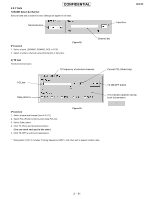
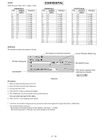
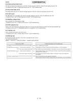
CONFIDENTIAL 4) RSSI Measure The handset notifies you of input power value at the aerial connector. GX30 Estimated Power Input box (Integer only) Measured power box Measure button Figure 65 [Procedure] 1. Connect the handset and GSM tester (or Signal Generator) with RF cable. 2. Select a band and channel. [see 4.6.3.1)] 3. Send signals (*) from GSM tester. 4. Enter the value of input power from GSM tester in integers (from -10 to -110) considering RF cable loss. 5. Press the [Measure] button. 6. The result appears in Measured Power box. * The signal type from GSM tester must be either of two: 1. Continuous sine wave (without modulation) with the frequency as follows: (Frequency of the measured channel) + 67.708kHz. (Ex. channel: GSM 37ch → the result: 942.467708 MHz) Power: -110 to -10 dBm 2. BCCH signal of the measured channel Power: -110 to -10 dBm Result When the handset is properly calibrated, the error between "Estimated Power" and "Measured Power" is less than 3dB. 4.6.4 Termination Turn off the handset to ensure proper operations. 4.6.5 Trouble imfomation When switching DCS and PCS, change the channel number as well. Or the band does not change properly. Example: If you change DCS 512 CH to PCS 512 CH, the band remains DCS. 2 - 33
-
 1
1 -
2
-
3
-
4
-
5
-
6
-
7
-
8
-
9
-
10
-
11
-
12
-
13
-
14
-
15
-
16
-
17
-
18
-
19
-
20
-
21
-
22
-
23
-
24
-
25
-
26
-
27
-
28
-
29
-
30
-
31
-
32
-
33
-
34
-
35
-
 36
36 -
 37
37 -
 38
38 -
 39
39 -
 40
40 -
 41
41 -
 42
42 -
 43
43 -
 44
44 -
 45
45 -
 46
46 -
47
-
48
-
49
-
50
-
51
-
52
-
53
-
54
-
55
-
56
-
57
-
58
-
59
-
60
-
61
-
62
-
63
-
64
-
65
-
66
-
67
-
68
-
69
-
70
-
71
-
72
-
73
-
74
-
75
-
76
-
77
-
78
-
79
-
80
-
81
-
82
-
83
-
84
-
85
-
86
-
87
-
88
-
89
-
90
-
91
-
92
-
93
-
94
-
95
-
96
-
97
-
98
-
99
-
100
-
101
-
102
-
103
-
104
-
105
-
106
-
107
-
108
-
109
-
110
-
111
-
112
-
113
-
114
-
115
-
116
-
117
-
118
-
119
-
120
-
121
-
122
-
123
-
124
-
125
-
126
-
127
-
128
-
129
-
130
-
131
-
132
-
133
-
134
-
135
-
136
-
137
-
138
-
139
-
140
-
141
-
142
-
143
-
144
-
145
-
146
-
147
-
148
-
149
-
150
-
151
-
152
-
153
-
154
-
155
-
156
-
157
-
158
-
159
-
160
-
161
-
162
-
163
-
164
-
165
-
166
 |
 |
