Sharp LC-22DV24U LC-22DV24U Operation Manual - Page 26
Connecting, Personal, computer
 |
UPC - 074000371125
View all Sharp LC-22DV24U manuals
Add to My Manuals
Save this manual to your list of manuals |
Page 26 highlights
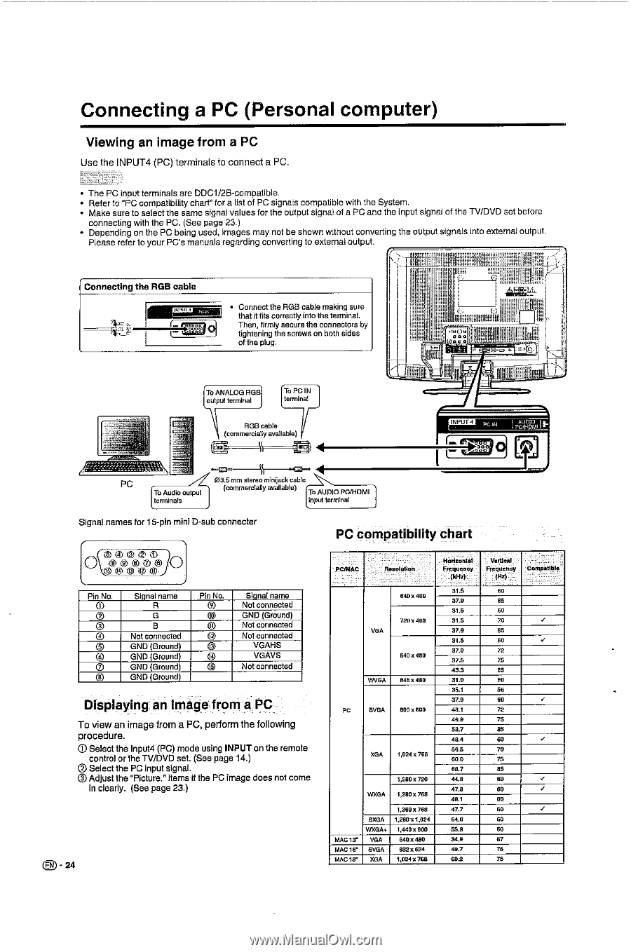
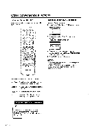
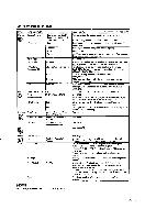
Connecting a PC (Personal computer) Viewing an image from a PC Use the INPUT4 (PC) terminals to connect a PC. • The PC input terminals are DDC1/2B-compatible. • Refer to "PC compatibility chart" for a list of PC signals compatible with the System. • Make sure to select the same signal values for the output signal of a PC and the input signal of the TV/DVD set before connecting with the PC. (See page 23.) • Depending on the PC being used, images may not be shown without converting the output signals into external output. Please refer to your PC's manuals regarding converting to external output. 1°![1111.11n ld.i,! Connecting the FIGB cable sa Connect the RGB cable making sure that it fits correctly into the tetminal. Then, firmly secure the connectors by tightening the screws on both sides of the plug. eCn coo leen EM! To ANALOG RGB output terminal To PG IN terminal ROB cable (commercially available) Yfl INPUT 4 41 PC 03(5 mm stereo mi ack To A clio output (commercially available) To AUDIO PWHOMI terminals input terminal Signal names for 15-pin mini D-sub connecter e_ oemo O 6e®m© e®o® sO Pin No. 0 ® 0 ® C) 0 0 ® Signal name R G B Not connected GND (Ground) GND (Ground) GND (Ground) GND (Ground) Pin No. ® § © ® © © 0 Signal name Not connected GND (Ground) Not connected Not connected VGAHS VGAVS Not connected Displaying an image from a PC To view an image from a PC, perform the following procedure. Qi Select the Input4 (PC) mode using INPUT on the remote control or the TV/DVD set. (See page 14.) iCt Select the PC input signal. © Adjust the "Picture." items if the PC image does not come in clearly. (See page 23.) 0 - 24 PC compatibility chart PO/SIAP Beethutlen Frequency Frequency Compatible 31.5 60 649x400 37.9 85 31.5 60 720 5400 31.5 70 VGA 3].9 85 31.5 60 a].9 72 640 x 481r 37.5 75 49.3 85 WVGA 8480480 300 60 35.1 56 37.9 60 PC SVGA 800 x 600 48.1 72 46.9 75 53.7 85 48.4 60 56.5 70 XGA 1,024 5768 60.0 75 66.7 85 1,280 x 720 44.6 60 i 47.8 50 WXGA 1280 x 766 46.1 60 1,360 x 768 07.7 60 SXGA 1,280 x 1,024 64,0 60 WXGAt 1,440x900 55.9 60 MAC 13" VGA 640x480 34.9 67 MAC 16' SVGA 832 x 624 49.7 75 MAC 19' XGA 1,024X]68 60.2 75
-
 1
1 -
2
-
3
-
4
-
5
-
6
-
7
-
8
-
9
-
10
-
11
-
12
-
13
-
14
-
15
-
16
-
17
-
18
-
19
-
20
-
 21
21 -
 22
22 -
 23
23 -
 24
24 -
 25
25 -
 26
26 -
 27
27 -
 28
28 -
 29
29 -
 30
30 -
 31
31 -
32
-
33
-
34
-
35
-
36
-
37
-
38
-
39
-
40
-
41
-
42
-
43
-
44
-
45
-
46
-
47
-
48
-
49
-
50
-
51
-
52
-
53
-
54
-
55
-
56
-
57
-
58
-
59
-
60
-
61
-
62
-
63
-
64
-
65
-
66
-
67
-
68
-
69
-
70
-
71
-
72
-
73
-
74
-
75
-
76
-
77
-
78
-
79
-
80
-
81
-
82
-
83
-
84
-
85
-
86
-
87
-
88
-
89
-
90
-
91
-
92
-
93
-
94
-
95
-
96
-
97
-
98
-
99
-
100
-
101
-
102
-
103
-
104
-
105
-
106
-
107
-
108
-
109
-
110
-
111
-
112
-
113
-
114
-
115
-
116
 |
 |