Sharp LC-26SB14U Service Manual - Page 10
: POWER PCB Refer to Fig. 1-6, 7: COVER LCD Refer to Fig. 1-7, 5: DIGITAL PCB Refer to Fig. 1-5, - no power
 |
View all Sharp LC-26SB14U manuals
Add to My Manuals
Save this manual to your list of manuals |
Page 10 highlights
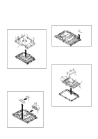
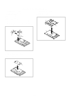
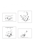
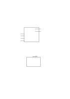
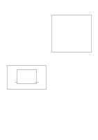
DISASSEMBLY INSTRUCTIONS 1-5: DIGITAL PCB (Refer to Fig. 1-5) 1. Disconnect the following connector: (CP3001 and CP4302). 2. Remove the 1 screw (1). 3. Remove the 5 screws (2). 4. Remove the 3 screws (3). 5. Remove the 1 screw (4). 6. Remove the Plate Jack in the direction of arrow (A). 7. Remove the 5 screws (5). 8. Remove the Digital PCB and Shield Digital in the direction of arrow (B). (2) (3) (1) (2) (4) (5) (5) (5) (5) (5) (A) Plate Jack Shield Digital Digital PCB 1-7: COVER LCD (Refer to Fig. 1-7) 1. Remove the 4 screws (1). 2. Remove the screw (2). 3. Remove the Cover LCD in the direction of arrow. (2) (1) (1) (1) (1) Cover LCD LCD Panel (B) Fig. 1-7 Fig. 1-6 1-6: POWER PCB (Refer to Fig. 1-6) 1. Remove the 5 screws (1). 2. Remove the Power PCB in the direction of arrow. (1) (1) (1) (1) (1) Power PCB Fig. 1-6 B1-2
-
 1
1 -
2
-
3
-
4
-
 5
5 -
 6
6 -
 7
7 -
 8
8 -
 9
9 -
 10
10 -
 11
11 -
 12
12 -
 13
13 -
 14
14 -
 15
15 -
16
-
17
-
18
-
19
-
20
-
21
-
22
-
23
-
24
-
25
-
26
-
27
-
28
-
29
-
30
-
31
-
32
-
33
-
34
-
35
-
36
-
37
-
38
-
39
-
40
-
41
-
42
-
43
-
44
-
45
-
46
-
47
-
48
-
49
-
50
-
51
-
52
-
53
-
54
-
55
-
56
-
57
-
58
-
59
-
60
-
61
-
62
 |
 |
