Sharp LC-26SB14U Service Manual - Page 9
Disassembly, Instructions - lcd parts
 |
View all Sharp LC-26SB14U manuals
Add to My Manuals
Save this manual to your list of manuals |
Page 9 highlights
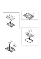
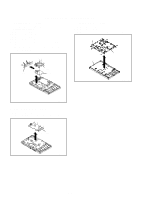
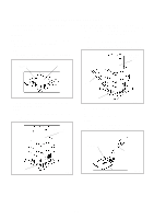
DISASSEMBLY INSTRUCTIONS 1. REMOVAL OF MECHANICAL PARTS AND P.C. BOARDS 1-1: BACK CABINET (Refer to Fig. 1-1) 1. Remove the 14 screws (1). 2. Remove the 7 screws (2). 3. Remove the Back Cabinet in the direction of arrow. (1)(2) (1) (1) (2)(2) (2) (1) (1) (1) (2) (2) (2) (1) (1) (1) (1) (1) (1) (1) (1) 1-3 REMOCON PCB (Refer to Fig. 1-3) 1. Disconnect the following connector: (CP4201). 2. Remove the 2 screws (1). 3. Remove the Remocon PCB in the direction of arrow (A). (1) (1) Remocon PCB (A) Fig. 1-3 Back Cabinet 1-4 LCD BLOCK (Refer to Fig. 1-4) 1. Disconnect the following connectors: (CP302, CP2804 and CP4303). 2. Remove the Holder Panel. 3. Remove the 4 screws (1). 4. Remove the LCD Block in the direction of arrow (A). 5. Remove the 4 screws (2). 6. Remove the Angle Main. Fig. 1-1 1-2: OPERATION PCB/OPERATION2 PCB and STAND ASS'Y (Refer to Fig. 1-2) 1. Disconnect the following connector: (CP6202). 2. Remove the Plate Button Ass'y in the direction of arrow (A). 3. Remove the 3 screws (1). 4. Remove the Operation PCB in the direction of arrow (B). 5. Remove the 2 screws (2). 6. Remove the 7 screws (3). 7. Remove the Angle Hinge in the direction of arrow (C). Holder Panel Angle Main (2) (2) (2) (2) (1) Angle Main (1) (1) LCD Block (1) (A) Holder Panel Plate Button Ass'y (1) (1) (1) (B) Operation PCB (3) (2) (3) (3) (A) (C) (3) (3) (3) Angle Hinge Fig. 1-4 Fig. 1-2 B1-1
-
 1
1 -
2
-
3
-
 4
4 -
 5
5 -
 6
6 -
 7
7 -
 8
8 -
 9
9 -
 10
10 -
 11
11 -
 12
12 -
 13
13 -
 14
14 -
15
-
16
-
17
-
18
-
19
-
20
-
21
-
22
-
23
-
24
-
25
-
26
-
27
-
28
-
29
-
30
-
31
-
32
-
33
-
34
-
35
-
36
-
37
-
38
-
39
-
40
-
41
-
42
-
43
-
44
-
45
-
46
-
47
-
48
-
49
-
50
-
51
-
52
-
53
-
54
-
55
-
56
-
57
-
58
-
59
-
60
-
61
-
62
 |
 |
