Sharp XL 1700 Service Manual
Sharp XL 1700 - Executive Microsystem Manual
 |
UPC - 074000412644
View all Sharp XL 1700 manuals
Add to My Manuals
Save this manual to your list of manuals |
Sharp XL 1700 manual content summary:
- Sharp XL 1700 | Service Manual - Page 1
system). MODEL XL-1700C XL-1700C Compact Audio System consisting of XL-1700C (main unit) and CP-XL1700U (speaker system). • In the interests of user-safety the set should be restored to its original condition and only parts identical to those specified should be used. CONTENTS Page IMPORTANT SERVICE - Sharp XL 1700 | Service Manual - Page 2
XL-1700/1700C FOR A COMPLETE DESCRIPTION OF THE OPERATION OF THIS UNIT, PLEASE REFER TO THE OPERATION MANUAL. IMPORTANT SERVICE NOTES (FOR U.S.A. ONLY) BEFORE RETURNING THE AUDIO PRODUCT (Fire & Shock Hazard) Before returning the audio product to the user, perform the following safety checks. 1. - Sharp XL 1700 | Service Manual - Page 3
and Down Buttons 12. CD Play or Pause, Tuning Up Button XL-1700/1700C 5 8 s Display 1. Timer Play Indicator 2. Sleep Indicator 3. CD Random Play Indicator 4. Memory Indicator 5. FM Stereo Mode Indicator 6. CD Play Indicator 7. CD Repeat Play Indicator 8. FM Stereo Receiving Indicator 9. Surround - Sharp XL 1700 | Service Manual - Page 4
XL-1700/1700C 1 2 3 4 5 6 7 8 9 10 11 12 13 17 18 21 14 15 19 22 16 20 23 24 25 26 27 s Remote control 1. Remote Control Transmitter 2. Power Button 3. CD Button 4. Tuner Button 5. Timer Button 6. Clock Button 7. Memory Button 8. Dimmer Button 9. Surround Button 10. Volume Up and Down - Sharp XL 1700 | Service Manual - Page 5
Setting the clock OPERATION MANUAL XL-1700/1700C 3 Within 1 minute, press the PRESET ( or ) button to adjust the hour and then press the MEMORY button. This may be operated only with the remote control. In this example, the clock is set for the 12-hour (AM12:00) display. 1 Press the CLOCK button - Sharp XL 1700 | Service Manual - Page 6
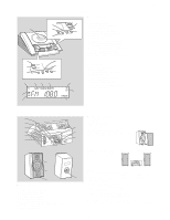
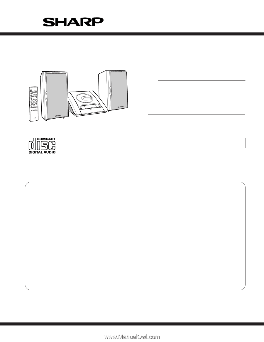
XL-1700/1700C 1 Accessories Accesorios AC power cord x1 Cable de alimentación de CA x1 Remote control x1 Controlador remoto x1 AM loop antenna x1 Antena de cuadro de AM x1 FM antenna x1 Antena de FM x1 Speaker wire x2 Cable del altavoz x2 2 Battery installation of remote your system stereo transmission - Sharp XL 1700 | Service Manual - Page 7
ensure excellent performance: 1. Take compact disc out of the unit. servicing. (A1) x2 ø3 x10mm (B1) x1 ø3 x10mm (B1) x1 ø3 x6mm Top Cabinet (C2) x4 ø3 x10mm XL-1700 x2 3. Socket G3) x2 8 CD PWB 1. Flat Cable H1) x1 8-2 2. Socket H2) x2 3. Screw H3) x4 9 CD Mechanism 1. Screw J1) x4 8-2 - Sharp XL 1700 | Service Manual - Page 8
XL-1700/1700C (E2) x1 (G3) x2 (G2) x2 ø3 x10mm (E2) x1 (G1) x5 ø3 x8mm Main PWB (E1) x2 ø3 x10mm Terminal PWB Rear Panel (F1) x1 ø3 x6mm (D1) x1 ø3 x10mm Tuner PWB (D2) x1 (H1) x1 CD PWB (L2) x1 Hook (N1) x3 Hook (L1) x2 CD Mechanism (H2) x1 Display PWB Top Cabinet Figure 8-2 (M1) - Sharp XL 1700 | Service Manual - Page 9
XL-1700/1700C REMOVING AND REINSTALLING THE MAIN PARTS How to remove the CD lid (See Fig. 9-1.) Perform steps 1 to 13 of the disassembly method to remove the gear box.(See page 7,8) 1. Remove the screws (A1) x 2 pcs., to remove the CD lid motor. 2. Remove the hooks (A2) x 3 pcs., to remove the - Sharp XL 1700 | Service Manual - Page 10
XL-1700/1700C TUNER SECTION ADJUSTMENT fL: Low-range frequency fH: High-range frequency • AM AM IF AM Band Coverage AM Tracking 450 kHz - 990 kHz 1,620 kHz 522 kHz 990 kHz Setting/ Instrument Adjusting Connection Parts T351 *1 (fL): T306 *2 1.1 ± 0.1 V (fL): T302 *1 *1. Input: Antenna, - Sharp XL 1700 | Service Manual - Page 11
XL-1700 POWER on with remote control buttons, test modes are not obtained. [Ordinary test mode] 1. CD Test Mode ( SET + PLAY Processes are different depending on destinations at initial settings. 2. CD Test Mode (TEST 1) In the CD inner periphery is completed at this time. If PICKUP IN SW ON cannot - Sharp XL 1700 | Service Manual - Page 12
XL-1700/1700C 2. Step 2 Mode Press the "CD PLAY" button in this mode to transmit the laser to wait for the following buttons to be pressed. (The disc is rotated for CLV lock.) The time display always indicates "0:00". Press the following buttons in this state to obtain the operations specified below. - Sharp XL 1700 | Service Manual - Page 13
XL-1700/1700C 5. Step 5 Mode When the CD initialization operation flow is completed, the mute is turned off, and playback is started. Even if playback reaches the outermost periphery of disc, the operation does not stop. The LCD display indicates the playback passage time as in case of ordinary CD - Sharp XL 1700 | Service Manual - Page 14
XL-1700/1700C 7. Step 7 Mode Press "MEMORY" key during step 6 operation to display automatically adjusted values on LCD in the order as below. Item names are displayed - Sharp XL 1700 | Service Manual - Page 15
XL-1700/1700C 3. Tuner Test Mode (TEST 2) 1. Outline of tuner (radio) test mode The tuner test mode is intended to store the adjustment and measurement frequencies in the preset memory CH. When adjusting the tuner section in the production line, adjusting personnel are not required to set CD STEREO - Sharp XL 1700 | Service Manual - Page 16
XL-1700/1700C 4. Electronic volume Test Mode (TEST 3) When this test mode is obtained, the following display lights for one second. In this mode, volume is -14 dB (STEP28), BASS/TREBLE is set to 0 (0 dB) and SURROUND mode to OFF, and start-up function to CD, respectively. The button operations in - Sharp XL 1700 | Service Manual - Page 17
is displayed. XL-1700/1700C This SET, REW, FF, STOP, CD-OPEN/CLOSE The OK/NG display of test result is as follows. 8. Electric CD lid Aging Test Mode (TEST 8) (Only for model with electric CD lid) Outline OPEN/CLOSE operations of electric CD lid are repeated. The number of repeated times and time - Sharp XL 1700 | Service Manual - Page 18
XL-1700/1700C NOTES ON SCHEMATIC DIAGRAM • Resistor: To differentiate the units of AM mode : FM stereo mode 2. In the CD section, the CD is stopped. • Parts marked with " " ( ) are important for maintaining the safety of the set. Be sure to replace these parts with specified ones for - Sharp XL 1700 | Service Manual - Page 19
9 10 11 XL-1700/1700C TUNER PWB SYSTEM MICROCOMPUTER/ FL DRIVER CD-STB 66 CD REMOTE SENSOR Q707 Q708 Q709 SWITCHING Q706 SWITCHING P_STB 1 1 PROTECT 2 2 CNW703 CE 1 1 DI 2 2 CL 3 3 DO 4 4 STEREO 5 5 SD 6 6 VSM 7 7 DATA 8 8 CLE 9 9 D_GND 10 10 P_MUTE 11 11 CD - Sharp XL 1700 | Service Manual - Page 20
XL-1700/1700C CD PWB FROM DISPLAY PWB 10 9 8 7 6 5 4 3 2 1 CNP704 CD_STB CD_RES CCE BUCK BUS3 BUS2 + VO3- GND VIN1 VO1+ VO1- IC803 MM1469PH FOCUS/ TRACKING/ SPIN/SLED DRIVER M_GND SO401 SUB WOOFER OUT VIDEO/AUX INPUT R-CH L-CH SP+ SP- SL+ SL- PU-IN GND M701 SPINDLE MOTOR + M - M + - Sharp XL 1700 | Service Manual - Page 21
XL-1700/1700C D_GND A_12V TUN L A_GND TUN R CE DI CL DO FM ST SD D_GND P_MUTE CD +B SURROUND M PWB 5 4 3 2 1 +B4 CNP803 CD_L 1 2 CD_R 3 A_GND UP UNIT 78 IC201 KIA4558P SURROUND 4 3 2 1 CONTROL MAIN PWB L-CH OUT AUX R R-CH OUT TUN R CD R 15 14 13 12 11 10 9 8 7 6 5 4 3 2 1 L-CH IN VSS CE - Sharp XL 1700 | Service Manual - Page 22
0.022 2.1V 4 5 6 R352 1K 0V 5V VSM C364 AM IF IN AM GND LOW CUT 0V (0.9V) 4.7/25 C365 0.022 FM/AM SD OUT 7 8 5V STEREO R353 FM DET 270 2.9V MPX VCO C367 1/50 R350 2.7K X351 2 3V456kHz C366 0.001 D301 1N4148 D302 1N4148 B C329 0.022 A XL-1700/1700C - Sharp XL 1700 | Service Manual - Page 23
16 15 14 13 C353 FM/AM 0.022 SD OUT 5V C354 0.022 5V STEREO C367 1/50 R350 2.7K 7 8 CF351 R353 FM DET X351 FM IF 270 M 8 Q360 KTA1266 GR 10.8V D308 1N4148 9 Figure 23 SCHEMATIC DIAGRAM (2/8) - 23 - 10 XL-1700/1700C AM SIGNAL FM SIGNAL SD 11 FM ST 10 DO 9 CL 8 DI 7 CE 6 D_GND - Sharp XL 1700 | Service Manual - Page 24
C823 C822 0.1 100/10 XL-1700/1700C A CD PWB-A3 CD PICK-UP UNIT (308) B HPC VO3+ V03- PO1+ PO1- C803 330/10 C804 0.022 VO1- VO1+ VIN1 VG1 TRB REG MUTE GND VG2 VIN2 V02+ V02- GND OPO E CD MOTOR PWB-C 1 2 3 4 5 6 7 8 9 10 11 12 13 14 R808 2.2K R810 2.2K CNP703A + M M701 SPINDLE MOTOR - - Sharp XL 1700 | Service Manual - Page 25
XL-1700/1700C P27 11-D CNW804 TERMINAL PWB-A4 CNW704 DISPLAY PWB-A2 P28 2-B C814 0.0068 +B C820 100/10 C821 0.022 R826 100 R837 10K C816 0.022 L801 2.2µH L802 2.2µH C822 100/10 FROM CD SIGNAL R870 10K R841 10K R842 10K R843 10K R844 10K R848 1K R849 1K CD_STB 10 CD_RES 9 CCE 8 BUCK 7 - Sharp XL 1700 | Service Manual - Page 26
XL-1700/1700C AMP_DET R755 1K DISPLAY PWB-A2 A +B +B LCD701 FL DISPLAY 1 2 3 4 5 6 7 8 9 10 11 12 13 14 15 16 17 18 19 20 21 B SW727 SW720 CLEAR VOLUME UP R706 1.5K VOLUME DOWN SW719 R716 10K MEMORY/ SET SW726 CD 50 R7A5 10K Q702 R7B0 10K REMOTE SENSOR RX701 R7A3 100 1K 1K - Sharp XL 1700 | Service Manual - Page 27
XL-1700/1700C +B LCD701 FL DISPLAY 14 15 16 17 18 19 20 21 R786 47K CLE R789 47K STEREO SD P_STB P_MUTE SURROUND CE CL DO DI CLID_SW CD+B B-LIGHT CE 1 1 DI 2 2 CL 3 3 DO 4 4 STEREO 5 5 SD 6 6 7 7 8 8 9 9 D_GND 10 10 P_MUTE 11 11 CD+B 12 12 SURROUND 13 13 - Sharp XL 1700 | Service Manual - Page 28
XL-1700/1700C A MAIN PWB-A1 FROM TUNER PWB-B1 CNS301 P23 11-D,E 11 10 9 8 7 6 5 4 3 2 1 CNP301 FRO DISPLAY CNW7 P27 1 1234 56 7 SD FM ST DO CL DI CE D_GND A_12V TUN_L A_GND TUN_R CE DI CL DO FM ST SD TO CNP804 CD PWB-A3 P25 12-C TERMINAL PWB-A4 J801 1 CD DIGITAL OUT - Sharp XL 1700 | Service Manual - Page 29
L102 3µH R130 6.8 C124 0.0022 R128 330 L105 10µH R127 330 +B 1 3 2 Q109 KRC107 M 3 2 Q108 1 +B KRA107 M XL-1700/1700C CNW707 P27 11-G FROM DISPLAY PWB-A2 CNW808 P25 12-F FROM CD PWB-A3 CNP707 1 2 CHASSIS GND CNP808 1 2 CHASSIS GND CNP909 1 1 2 2 CHASSIS GND C691 0.01 FROM - Sharp XL 1700 | Service Manual - Page 30
R812 XL-1700/1700C TO MAIN PWB-A1 A CNP805 P32 6-F GY GY GY GY GY WH - B 654321 654321 CNP703A M702 SLED MOTOR C SW702 PICKUP IN + M701 D SPINDLE MOTOR CD MOTOR -A1 CNP803 P33 8-H TO MAIN PWB-A1 CNP703 P33 8-D 2 3 CD PWB-A3 D801 ZD801 R826 2 C821 C820 D806 D805 CNW808 1 R807 - Sharp XL 1700 | Service Manual - Page 31
XL-1700 6 7 CD PICKUP UNIT (308) 1 3 5 7 9 11 13 15 2 4 6 8 10 12 14 16 SW802 CD LID R867 2 CNP706 1 R866 5 12 SWITCH PWB-A5 M801(246-6) CD LID OPEN/ Q806 R773 SW728 C713 C714 32 1 RX701 R708 1 CFW702 C715 CLEAR MEMORY/ SET BASS/ TREBLE 2 FUNCTION BK GY 1 GY 2 GY 3 4 GY 5 - Sharp XL 1700 | Service Manual - Page 32
XL-1700/1700C J801 CD DIGITAL OUTPUT SUB WOOFER OUT SO401 VIDEO/AUX INPUT RIGHT LEFT A CHASSIS TERMINAL PWB-A4 GND 231 C866 L804 C865 CNW804 1 3 C864 R406 R408 C137 L106 CNW401 3 1 2 1CNW101 L401 CHASSIS GND MAIN - Sharp XL 1700 | Service Manual - Page 33
XL-1700/1700C PWB-A1 JK101 HEADPHONES JACK RIGHT SO601 SPEAKER 4 3 2 1 R686 R685 C691 Q683 B C E 2 1 CNP909 CHASSIS GND FROM CD PWB-A3 CNW803 P30 5-C CHASSIS FROM DISPLAY PWB-A2 CNW702 GND FROM CNW808 CD PWB-A3 P31 8,9-F P30 4-A CNW701 FROM DISPLAY P31 11-F PWB-A2 R417 R418 7 - Sharp XL 1700 | Service Manual - Page 34
XL-1700/1700C WAVEFORMS OF CD CIRCUIT NO DISC FOCUS SEARCH 1 FOO IC801 33pin 2 FO+ IC803 26pin 3 FO- IC803 25pin FOCUS SEARCH TOC IL 4 SEL IC801 38pin 5 FEI IC801 29pin 6 TEI - Sharp XL 1700 | Service Manual - Page 35
XL-1700/1700C TROUBLESHOOTING When the CD does not function When the CD and follow the troubleshooting instructions. "Track avoid this problem, use a cleaning disc designed for CD optical pickup disc. If the CD cleaner brushes become CD cleaner disc must not be used on car CD player or on computer CD - Sharp XL 1700 | Service Manual - Page 36
XL-1700/1700C Make sure that the disc is normal, and set the CD TEST MODE (STEP 1). Is the measured voltage as MOTOR Yes OPERATING FAILURE ". Check the procedure "NO SOUND" Does the LCD track number and time indicator work properly ? Yes Turn the power off and then back on. Does the unit - Sharp XL 1700 | Service Manual - Page 37
the cathode side of ZD801 ? Yes XL-1700/1700C Check the PWB pattern between emitter of Q605 and CNP805/ No CNW805. Check the peripheral parts of ZD801,C820 and C821. No following waveform output at the pin 29 (FEI) of IC801 when the disc is set? Yes pin 29 (FEI) pin 33 (FOO) pin 30 (SBAD) Is - Sharp XL 1700 | Service Manual - Page 38
XL-1700/1700C • Focus servo sawtooth wave failure. Is sawtooh wave output to the pin 33 ( IC803. No • Spindle motor clv servo failure. Is following wave output to the pin 41 (DMO) of IC801 when the CD TEST MODE "STEP 3" is changed to " STEP 4" ? Yes DMO Check the procedure in "HF ERROR". No If - Sharp XL 1700 | Service Manual - Page 39
XL-1700/1700C • HF error. Is output (tracking error signal) obtained at the pins 31 (TEI) and 32 (TEZI) of IC801 the CD TEST MODE "STEP 4" is changed to "STEP 5"? Yes test mode "step 4" between pin 51 of IC801 and Q808. No Check the peripheral parts of IC801. If OK, IC801 is faulty. No - 39 - - Sharp XL 1700 | Service Manual - Page 40
XL-1700/1700C • Track search failure Does the sled motor run in FF/REW state when the SERVO TEST MODE "STEP1" is set? CD mechanism (periphery of sled motor). If the sled motor does not run when DC2.0V is applied to both terminals of sled motor, the sled motor is faulty. Check the peripheral parts - Sharp XL 1700 | Service Manual - Page 41
XL-1700/1700C FUNCTION TABLE OF IC Serial data and clock input pin for control. Chip enable pin. Data written into an internal latch in a timing of [H] -> [L]. Each analog switch is activated. Data transfer enabled at [H] level. Ground pin. Electronic volume control pin. To be set - Sharp XL 1700 | Service Manual - Page 42
XL-1700/1700C IC401 VHiLC75342M-1: Function/Volume Equalizer (LC75342M) TEST VSS CE DI CL VDD Vref NC 4 3 2 1 30 29 28 27 LOUT 5 26 ROUT LBASS2 6 LBASS1 7 25 - Sharp XL 1700 | Service Manual - Page 43
LCD701: RV-LX0015SJZZ LCD Display XL-1700/1700C z1 z4 z2 r z3 q 1 2 3 4 5 6 7 8 9 10 11 12 13 14 15 16 17 18 19 20 21 22 23 24 25 26 27 28 29 - Sharp XL 1700 | Service Manual - Page 44
XL-1700/1700C -MEMO- - 44 - - Sharp XL 1700 | Service Manual - Page 45
PARTS GUIDE XL-1700/1700C COMPACT AUDIO SYSTEM MODEL XL-1700 XL-1700 Compact Audio System consisting of XL-1700 (main unit) and CP-XL1700U (speaker system). MODEL XL-1700C XL-1700C Compact Audio System consisting of XL-1700C (main unit) and CP-XL1700U (speaker system). "HOW TO ORDER REPLACEMENT - Sharp XL 1700 | Service Manual - Page 46
XL-1700/1700C NO. PART CODE PRICE RANK DESCRIPTION NO. PARTS CODE PRICE RANK /-1 VHIMM1469PH-1 VHITA7291S/-1 AN78L05 J AX System Microcomputer/FL Driver, IX0043SJ J AY TA2157F J Focus/Tracking/Spin/Sled Driver, MM1469PH J AH CD LID Motor Driver,TA7291S L101,102 L105 L106 L342 L351, - Sharp XL 1700 | Service Manual - Page 47
VCKYCY1EF223Z J AB 0.022 µF,25V RC-GZA107AF1A J AB 100 µF,10V,Electrolytic VCKYCY1EF223Z J AB 0.022 µF,25V RC-GZA107AF1A J AB 100 µF,10V,Electrolytic XL-1700/1700C NO. PARTS CODE PRICE RANK DESCRIPTION C809 C810,811 C812 C813 C814 C815,816 C817 C818 C819,820 C821 C822 C823,824 C825 C826 C827 - Sharp XL 1700 | Service Manual - Page 48
XL-1700/1700C NO. R201 R202 R203,204 R205,206 R207 R208 R209,210 R211 R441 R442 R601 R602 R603 R604 R605 R606 R607 R608 R609 R610 R611 R612 R685 R686 R702 R703 PART CODE PRICE RANK DESCRIPTION VRS-CY1JB822J VRD-ST2EE822J VRS-CY1JB104J VRS-CY1JB103J VRD-ST2CD473J VRD-ST2EE331J VRS-CY1JB103J VRS- - Sharp XL 1700 | Service Manual - Page 49
XL-1700/1700C NO. PART CODE PRICE RANK DESCRIPTION NO. PARTS CODE PRICE XL-1700] Bottom Cabinet [XL-1700C] Cover,Rear Panel AD Cover,Remote Sensor AG CD Lid AG Slide Door AD Badge,SHARP AT Cover Plate,CD Lid AN Plate,Slide Door AK Plate,CD Lid AH Sheet,Operation AF CD Ring Panel Clear Panel,CD - Sharp XL 1700 | Service Manual - Page 50
J Operation Manual [XL-1700] TINSK0031SJZZ J Operation Manual [XL-1700C] TINSZ0140SJZZ J Quick Guide 1 QACCU0003SJ00 J AC Power Supply Cord QANTL0001SJZZ J AK AM Loop Antenna QANTW0002SJZZ J AH FM Antenna QCNWH0005SJ01 J AF Speaker Cord RRMCG0037SJSA J AT Remote Control GCABB1064SJSB - Sharp XL 1700 | Service Manual - Page 51
XL-1700/1700C A 308-3 B 308 308-1 308-2 305 703 C 704 D 304 703 701 303 302 301 E 702x2 M701 F G 306x2 SW702 M702 307x2 H PWB-C 1 2 3 4 5 6 Figure 6 CD MECHANISM EXPLODED VIEW - 6 - - Sharp XL 1700 | Service Manual - Page 52
XL-1700/1700C 611 203 A 615x4 209 614x3 214 211 602x2 239 612 B 213 208 T651 A5 Q603 Q602 613x3 PWB-A4 PWB-A1 249 603 615x2 PWB-B1 224 234 242 LCD701 F 221 606 218 220 CD MECHANISM 202 PWB-B2 PWB-A6 241 231 607x4 219 217 230x2 220 PWB-A2 230x2 G 229 PWB-A7 606x6 - Sharp XL 1700 | Service Manual - Page 53
XL-1700/1700C A Tweeter 904 SP603 (L-CH) SP604 (R-CH) 904-1 904-3 Black White Line Red B 903 904-2 903-1 Black 904-4 Woofer SP601 (L-CH) SP602 (R-CH) C 901 907 D - Sharp XL 1700 | Service Manual - Page 54
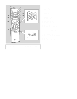
XL-1700/1700C PACKING OF THE SET (FOR U.S.A. ONLY) Setting position of switches and knobs CD Lid CLOSE AC Power Supply Cord FM Antenna AM Loop Antenna Speaker Cord Remote Control Polyethylene Bag,Speaker SPAKZ0039SJZZ Quick Guide Operation Manual Polyethylene Bag,Accessories SSAKA0009SJZZ - Sharp XL 1700 | Service Manual - Page 55
-MEMO- XL-1700/1700C - Sharp XL 1700 | Service Manual - Page 56
XL-1700/1700C COPYRIGHT © 2002 BY SHARP CORPORATION ALL RIGHTS RESERVED. No part of this publication may be reproduced, stored in a retrieval system, or transmitted in any from or by any means, electronic, mechanical, photocopying, recording, or otherwise, without prior written permission of the
-
 1
1 -
 2
2 -
 3
3 -
 4
4 -
 5
5 -
 6
6 -
 7
7 -
8
-
9
-
10
-
11
-
12
-
13
-
14
-
15
-
16
-
17
-
18
-
19
-
20
-
21
-
22
-
23
-
24
-
25
-
26
-
27
-
28
-
29
-
30
-
31
-
32
-
33
-
34
-
35
-
36
-
37
-
38
-
39
-
40
-
41
-
42
-
43
-
44
-
45
-
46
-
47
-
48
-
49
-
50
-
51
-
52
-
53
-
54
-
55
-
56
 |
 |
XL-1700/1700C
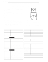
CONTENTS
Page
IMPORTANT SERVICE NOTES (FOR U.S.A. ONLY)
.....................................................................................................
2
SPECIFICATIONS
............................................................................................................................................................
2
NAMES OF PARTS
..........................................................................................................................................................
3
OPERATION MANUAL
.....................................................................................................................................................
5
DISASSEMBLY
.................................................................................................................................................................
7
REMOVING AND REINSTALLING THE MAIN PARTS
....................................................................................................
9
ADJUSTMENT
................................................................................................................................................................
10
TEST MODE
...................................................................................................................................................................
11
NOTES ON SCHEMATIC DIAGRAM
.............................................................................................................................
18
TYPES OF TRANSISTOR AND LED
..............................................................................................................................
18
BLOCK DIAGRAM
..........................................................................................................................................................
19
SCHEMATIC DIAGRAM
.................................................................................................................................................
22
WIRING SIDE OF P.W.BOARD
......................................................................................................................................
30
WAVEFORMS OF CD CIRCUIT
.....................................................................................................................................
34
TROUBLESHOOTING
....................................................................................................................................................
35
FUNCTION TABLE OF IC
..............................................................................................................................................
41
LCD SEGMENT
..............................................................................................................................................................
43
PARTS GUIDE/EXPLODED VIEW
PACKING OF THE SET (FOR U.S.A. ONLY)
SERVICE MANUAL
SHARP
CORPORATION
No. S4221XL1700//
• In the interests of user-safety the set should be restored to its original
condition and only parts identical to those specified should be used.
This document has been published to be used
for after sales service only.
The contents are subject to change without notice.
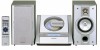
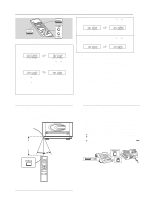
XL-1700 Compact Audio System consisting of XL-1700
(main unit) and CP-XL1700U (speaker system).
COMPACT AUDIO SYSTEM
MODEL
XL-1700
XL-1700C Compact Audio System consisting of XL-1700C (main
unit) and CP-XL1700U (speaker system).
MODEL
XL-1700C