Snapper S22675 Operater's Manual - Page 8
Assembly
 |
View all Snapper S22675 manuals
Add to My Manuals
Save this manual to your list of manuals |
Page 8 highlights
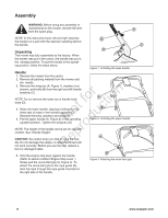
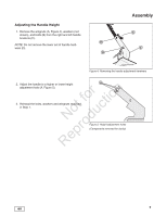
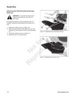
Assembly WARNING: Before doing any assembly or maintenance to the mower, remove the wire A from the spark plug. NOTE: In this instruction book, left and right describe B the location of a part with the operator standing behind the handle. C Unpacking The mower was fully assembled at the factory. When the mower was put in the carton, the handle was put in the storage position. To put the handle in the operating position, follow the steps below. D Figure 1: Unfolding the lower handle Handle 1. Remove the mower from the carton. 2. Remove all packing material from the mower and the handle. 3. Remove the wingnuts (A, Figure 1), washers (not shown), and bolts (B) from the right and left handle r n brackets (C). fo tio NOTE: Do not remove the lower set of handle hard- ware (D). t c 4. Raise the lower handle, aligning it with one of the o three sets of holes in the handle brackets (C). u Reinstall the bolts, washers and wingnuts. N d 5. Put the upper handle (A, Figure 2) in the operating (upright) position. Tighten the wingnuts (B). ro NOTE: The height of the handle can be set for operator comfort. See "Handle Height". p CAUTION: Be careful when you fold or raise the hane dle. Do not damage the cables. A cable that is bent will R not work correctly. Before you use the unit, replace a A B Figure 2: Unfolding the upper handle A bent or damaged cable. 6. Hold the engine stop lever against the handle. (Refer to section entitled 'Engine Stop Lever'.) Slowly pull the recoil-start grip (A, Figure 3). To attach the recoil-start grip to the rope guide (B), twist the rope through the rope guide mounted on the right side of the handle. B Figure 3: Attaching the recoil-start grip 8 www.snapper.com
-
 1
1 -
2
-
 3
3 -
 4
4 -
 5
5 -
 6
6 -
 7
7 -
 8
8 -
 9
9 -
 10
10 -
 11
11 -
 12
12 -
 13
13 -
14
-
15
-
16
-
17
-
18
-
19
-
20
-
21
-
22
-
23
-
24
-
25
-
26
-
27
-
28
-
29
-
30
-
31
-
32
-
33
-
34
-
35
-
36
-
37
-
38
-
39
-
40
-
41
-
42
-
43
-
44
-
45
-
46
-
47
-
48
-
49
-
50
-
51
-
52
-
53
-
54
-
55
-
56
-
57
-
58
-
59
-
60
-
61
-
62
-
63
-
64
-
65
-
66
-
67
-
68
-
69
-
70
-
71
-
72
-
73
-
74
-
75
-
76
-
77
-
78
-
79
-
80
 |
 |
